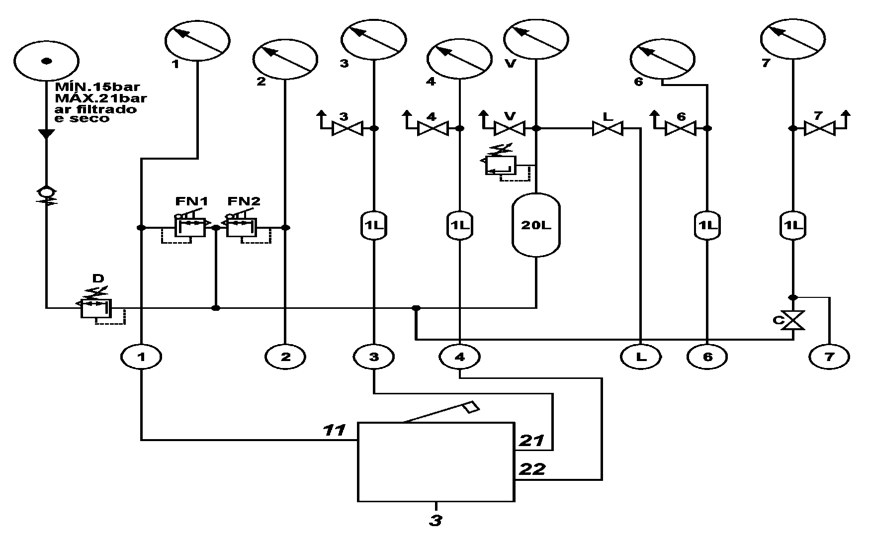
Stand accessories D = Pressure reducing valve. FN1 = Pressure regulating valve (fine adjustment) with discharge to atmosphere. Actuates stand circuit 1. V = Stand supply manometer. 1 = 3 = 4 = Manometers with 0.10 bar scale division, 16 bar capacity. Indicates the test circuits pressure. 20L = Air reservoir with 20-liter capacity. C = V = Faucet (taps). (1) = (3) = (4) = Quick connections available on the stand. | |
Visual check Check the valve for external damages. | |
Connect the valve on the bench Install the angle measuring device, mount the valve on the bench according to the corresponding diagram and connect: Quick clamping device (1) (test stand) to connection 11 Quick clamping device (3) (test stand) on connection 21 Quick clamping device (4) (test stand) on connection 22 |
B42.20-0007-12
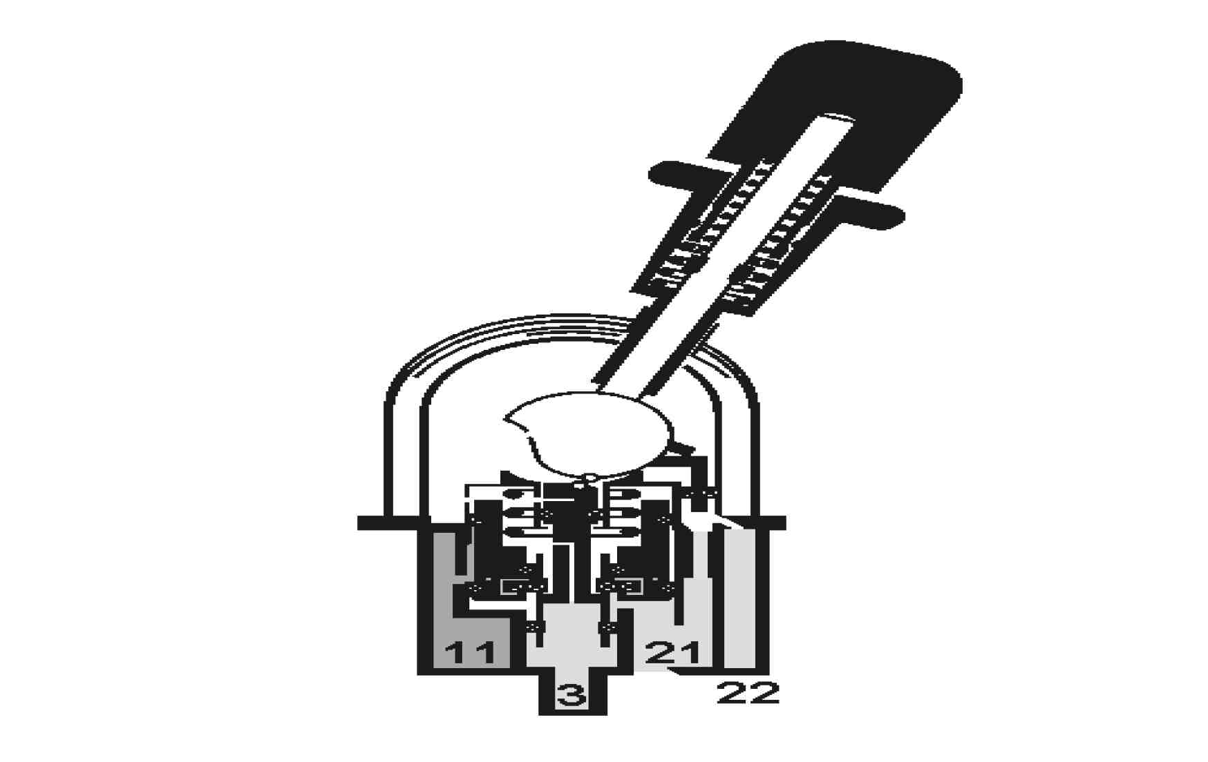
4 | Test for tightness Actuate valve FN1 until manometer 1 indicates 8 bar. With the valve handle in the brake released position (handle released) check the pressure reading on manometers 3 and 4 which should be 8 bar. Check for leaks in the areas where the body joins and exhausts (discharge) Position activated: Activate the valve FN1 until the manometer 1 reaches a pressure of 8 bar. With the valve handle in the brake applied position (handle locked) check the pressure reading on manometers 3 and 4 which should be: Manometer 3 pressure of 0 bar. Manometer 4 pressure of 8 bar. Check for leaks in the body junction and exhaust (discharge) areas. Note: In the event of leaks, dismantle the valve and replace the damaged components. |
5 | Test for operation Actuate valve FN1 until manometer 1 indicates 8 bar. Move the valve wrist up to an angle of 20° from the released brake position (released wrist). Check the pressure reading on manometer 3 which should be within 4.1 and 4.8 bar. Move the valve handle to an angle of 50° from the brake released position (handle released). Check the pressure readings on manometers 3 and 4 which should be “0” (zero) bar. With an approximately 90° angle the locking of the handle should occur and the pressure reading on manometer 3 will have to be “0” (zero) bar and on manometer 4 will have to be 8 bar. |
6 | Test the electric connector Feed the electric connector with a current of 12 V. Move the valve wrist to the released brake position (released wrist). Check the contact, which must be opened. Move the valve wrist to the actuated brake position (locked wrist). Check the electric contact, which must be closed. |
7 | Remove the valve from the test stand De-pressurize the valve circuits and disconnect the test hoses. Disconnect the electric cables. Remove the valve from the device and from the stand and cover the ports with the appropriate plastic plugs. |
B42.20-0011-02