AR35.50-W-0016A | Remove/install lift bellows of trailing axle | 15.3.12 |
REAR AXLE 749.916 in MODEL 958.0
REAR AXLE 749.919 in MODEL 958.2
REAR AXLE 749.919 /921 in MODEL 958.4
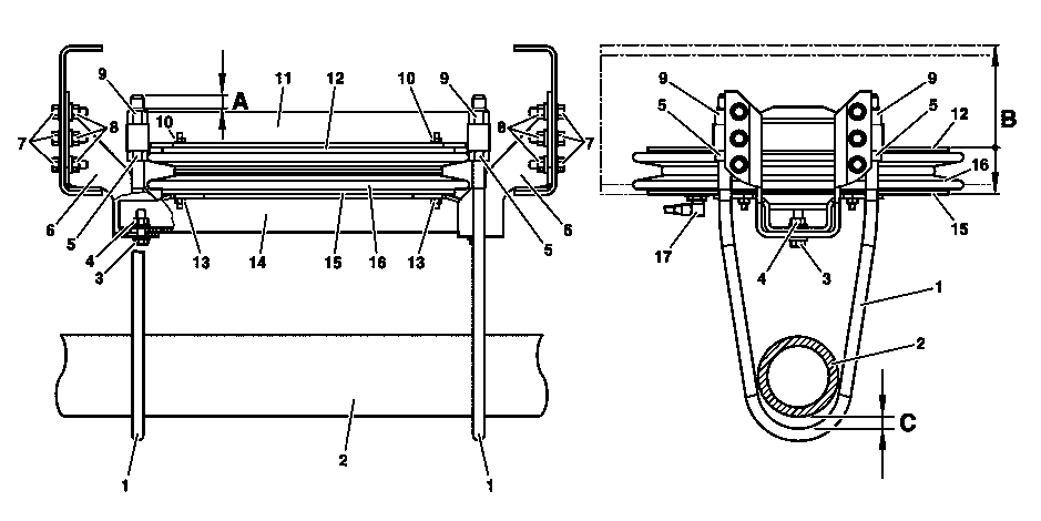
B35.50-0004-09
1 Bracket
2 Axle tube
3 Screw
4 Nut
5 Nut
6 Bearing brackets
7 Bolts
15 Base
16 Lift bellows
17 Compressed-air line
A Thread projection
B Travel
C Play
8 Nuts
9 Nut
10 Nut
11 Crossmember
12 Base
13 Nut
14 Crossmember
Modification notes
| Removing | ||
| Notes on self-locking nuts and bolts | ||
1 | Park vehicle on a level surface above pit | Perform all work with vehicle unloaded. | |
2 | Lower liftable trailing axle completely | ||
3.1 | Interrupt power supply using battery disconnect switch | ||
Danger! | Risk of explosion caused by escaping oxyhydrogen gas. Risk of injury caused by caustic burns to eyes, skin and mucous membranes from battery electrolyte (contains diluted sulfuric acid) or metal spatter due to short circuit. Risk of burn injuries caused by short circuit. Risk of poisoning caused by swallowing battery electrolyte (contains diluted sulfuric acid) or absorption of lead over the skin or orifices | No fire, sparks, open flames or smoking. Wear acid-resistant gloves and clothing and safety glasses with side guards. Do not place any conductive objects on the battery and avoid any short circuit from battery positive to ground. Only fill liquid battery electrolyte (diluted sulfuric acid) into suitable and appropriately marked containers. | |
3.2 | Disconnect ground lead from battery | Only vehicles without battery disconnect switch. | |
| Notes on battery | ||
4 | Disconnect compressed air line (17) from lifting device | Take measures to prevent dirt from entering the openings. | |
5 | Unscrew nuts (9) and remove brackets (1) | Check the brackets (1) for wear. | |
6 | Remove crossmember (11) with base (12) | Use an assembly lever. If the crossmember (11) and base (12) do not detach from the lift bellows (16), unscrew the nuts (10) and remove the crossmember (11) from the base (12). | |
7 | Remove lift bellows (16). | Check the contact surfaces between the bases (12, 15) and lift bellows (16) for damage and corrosion; replace damaged parts. | |
If the lift bellows (16) does not detach from the base (15), unscrew the nuts (13) and remove the base (15) with the lift bellows (16) from the crossmember (14). | |||
8 | Unscrew bolts (3) and nuts (4) and remove crossmember (14) | Only if the base (15) was removed. | |
9 | Unscrew bolts (7) and nuts (8) and remove mounting consoles (6) | Check the mounting consoles (6) for deformation and cracks; replace if necessary. | |
| Checking | ||
10 | Clean all components and check them for damage and cracks | Replace damaged parts. | |
| Install | ||
11 | Install mounting consoles (6) | Model 958.0 | |
Model 958.2/4 | |||
12 | Attach base (15) to crossmember (14) | Only if the base (15) was removed from the crossmember (14). | |
13 | Install crossmember (14) with base (15) | Only if the base (15) was removed. | |
Model 958.0 | |||
Model 958.2/4 | |||
14 | Attach lift bellows (16) to base (15) | ||
15 | Attach base (12) to crossmember (11) | Only if the base (12) was removed from the crossmember (11). | |
16 | Install crossmember (11) with base (12) | ||
17 | Screw nuts (5) onto new brackets (1) (position of nuts must correspond to their previous position on removed brackets (1)) | Only if new brackets (1) are used. | |
18 | Install brackets (1) and tighten nuts (9) | ||
19 | Connect compressed air line (17) to lifting device | ||
| Checking | ||
20 | Measure play (C) between the brackets (1) of the lifting device and the axle tube (2) of the trailing axle | If the play (C) does not match the specified value: | |
Adjust play (C) | |||
The play (C) must be adjusted so that the travel (B) does not become too great and does not cause leakage at the lift bellows (16). | |||
Check/adjust lift bellow brackets on liftable trailing axle | |||
21 | Tighten nuts (9) to specified torque | Model 958.0 | |
Model 958.2/4 | |||
22 | Measure thread projection (A) at brackets (1); cut off projecting thread if necessary | The thread projection (A) must not exceed approx. 10 mm. | |
Danger! | Risk of explosion caused by escaping oxyhydrogen gas. Risk of injury caused by caustic burns to eyes, skin and mucous membranes from battery electrolyte (contains diluted sulfuric acid) or metal spatter due to short circuit. Risk of burn injuries caused by short circuit. Risk of poisoning caused by swallowing battery electrolyte (contains diluted sulfuric acid) or absorption of lead over the skin or orifices | No fire, sparks, open flames or smoking. Wear acid-resistant gloves and clothing and safety glasses with side guards. Do not place any conductive objects on the battery and avoid any short circuit from battery positive to ground. Only fill liquid battery electrolyte (diluted sulfuric acid) into suitable and appropriately marked containers. | |
23.1 | Connect ground cable to battery | Only vehicles without battery disconnect switch. | |
| Notes on battery | ||
23.2 | Switch on power supply at battery disconnect switch | ||
Danger! | Risk of accident caused by vehicle starting off by itself when engine is running. Risk of injury caused by contusions and burns during starting procedure or when working near the engine as it is running | Secure vehicle to prevent it from moving by itself. | |
24 | Start engine and bring compressed air system up to operating pressure | ||
25 | Raise and lower liftable trailing axle several times to adapt components | Before actuating the lifting device, always check that the nuts (9) are fitted securely; loose nuts (9) can result in damage to the lift bellows (16). | |
Perform a leak test on the lifting device. |
Test values for steering axis
Number | Designation | Model 958.0 with rear axle 749.916 | Model 958.2 with rear axle 749.919 | ||
BE35.50-N-1001-02C | Travel "B" between supports of lifting device | Trailing axle raised | mm | 260 | 260 |
Trailing axle lowered, lifting device unpressurized | mm | 70 | 70 | ||
BE35.50-N-1002-02C | Play "C" between bracket and axle tube | VEH without load or body | mm | 10 | 10 |
VEH with body or semi-tractor | mm | 10...15 | 10...15 | ||
Test values for steering axis
Number | Designation | Model 958.4 with rear axle 749.919/921 | ||
BE35.50-N-1001-02C | Travel "B" between supports of lifting device | Trailing axle raised | mm | 260 |
Trailing axle lowered, lifting device unpressurized | mm | 70 | ||
BE35.50-N-1002-02C | Play "C" between bracket and axle tube | VEH without load or body | mm | 10 |
VEH with body or semi-tractor | mm | 10...15 | ||
Air suspension
Number | Designation | Model | ||
BA32.22-N-1004-03B | Lift bellows support to mounting console | Nm | 125 | |
BA32.22-N-1005-03B | Mounting console to frame | M12 | Nm | 115 |
M14 | Nm | 165 | ||
BA32.22-N-1006-03B | Bracket to lift bellows | Nm | 280 | |
Air suspension
Henviste dokumenter
- ah0000n000101a Oplysninger om selvlåsende bolte og møtrikker
- ah5410p000101a Oplysninger om batterier
- ah5410p000101a
- ar3550w359301a
- as0000z000501a Fare for ulykke ved automatisk igangsætning når motoren kører. Fare for personskade på grund af knusning og forbrænding, hvis der arbejdes mens motoren startes eller kører
- as5410z000101a Brand-/eksplosionsfare på grund af kortslutning og udsivende knaldgas. Forbrændingsfare/fare for personskade ved ætsning af øjne, hud og sliminder på grund af batterielektrolyt/-tåge, kortslutning og lysbuepåvirkning. Fare for