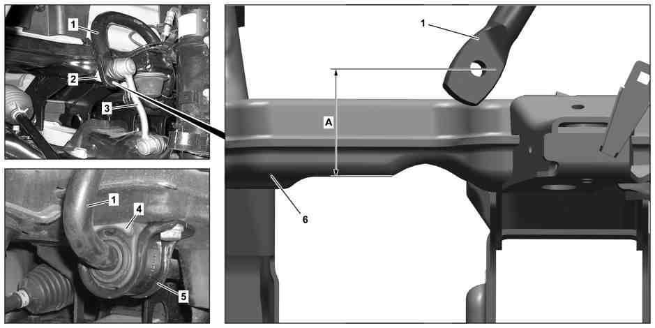
D32.20-1134-09
1 Stabilizer bar
2 Nut
3 Torsion bar linkage
A Installed dimension
4 Rubber bushing
5 Bearing shell
6 Front axle
| Removing | ||
1 | Lift/jack up vehicle | ||
2 | Detach left and right torsion bar linkage (3) from stabilizer bar (1) | ||
3 | Remove bearing shells (5) and rubber mount (4) from torsion bar (1) | ||
| Modified rubber mount on front-axle stabilizer bar | Model 906 | |
| Checking | ||
4 | Check rubber mounts (4) and bearing shells (5) for signs of wear and damage, replace if necessary | ||
| Install | ||
5 | Mount bearing shell (5) and rubber mount (4) to torsion bar (1) | For torsion bar (1) with torsion rubber mount: Tighten bolts of bearing shells (5) only after adjusting torsion bar (1) with torque. | |
| |||
6 | Adjust and tighten stabilizer bar (1) | For torsion bar (1) with torsion rubber mount: Measured from lower edge of front axle (6) to center of mounting bore in torsion bar (1). | |
Installed dimension | |||
| |||
7 | Mount left and right torsion bar linkage (3) onto stabilizer bar (1) | Install new self-locking nut (2). | |
|
Test and adjustment values for front-axle torsion bar
Number | Designation | Model | |||
BE32.20-N-1001-05A | Assembly position | Front axle torsion bar | Dimension "A" | mm | 59,5 |
See picture | |||||
Test and adjustment values for front-axle torsion bar
Number | Designation | Model | |||
BE32.20-N-1001-05A | Assembly position | Front axle torsion bar | Dimension "A" | mm | 59,5 |
See picture | |||||
Test and adjustment values for front-axle torsion bar
Number | Designation | Model | |||
BE32.20-N-1001-05A | Assembly position | Front axle torsion bar | Dimension "A" | mm | 62,5 |
See picture | |||||
Front axle anti-sway bar