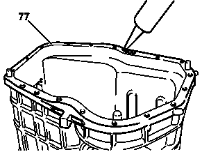
1 | Apply the silicone based sealant product on the extension, on the surface of contact with the front housing (77). |
B26.40-0020-01

2 | Assemble the front housing (77) over shaft sets, observing its flange correct settlement with the rear housing (74). |
All bars and assemblies must be in neutral. |
B26.40-0030-01

3 | Install two fastening screws of the housing (62) to the extension (74) for pre-fastening of the housing (77). |
Apply Loctite 262 seal on the screws. |
B26.40-0017-01

4 | Position the transmission horizontally and install the remaining screws (62) of the housing . |
Apply Loctite 262 seal on the screws. |
B26.40-0016-01

5 | Position the universal joint fork bridge (65) in the splined of the secondary shaft. |
B26.40-0035-01

6 | Install a new self-locking nut (66) of the universal joint fork (65). |
Apply Loctite 262 sealant to the self-locking nut. |
B26.40-0034-01

7 | Position the wedges for clearance adjustment (80 to 85) longitudinal to intermediate shaft. |
Use the same package of wedges removed during disassembly. Place the wedges of greater thickness on the external side. |
B26.40-0015-01

8 | Install the front cover of the intermediate shaft and the fastening screws. |
Do not apply the adhesive on the cover or on the bolt treads. |
B26.40-0029-01

9 | Position the wedges in the longitudinal clearance adjustment of secondary tree (46 to 51), along with the primary shaft seal assembly (42 to 45). |
Use the same thickness of shims removed during the dismount. |
Place the thicker wedges at the endpoints. |
B26.40-0014-01

10 | Install the fastening screws (40) from the primary shaft retainer. |
Do not apply the adhesive on the cover or on the bolt treads. |
B26.40-0012-01

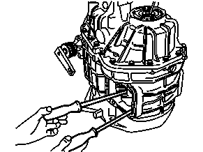
11 | With a dial indicator, measure the axial clearance of the intermediate shaft assembly, through the opening of it rear cover (69). |
Invert the transmission position. |
Use a inverted back cover as a dial indicator basis. |
Move the intermediate shaft through the opening of the power take off cover. |
B26.40-0021-01
B26.40-0022-01

12 | Measure the axial clearance of the secondary shaft assembly through the end of its notched axle (65). |
B26.40-0023-01

13 | Invert the transmission position and remove the front cover (87) of the intermediate shaft to have electronic access to the wedges. |
B26.40-0024-01
14 | Select a package of shims (80 to 85) of thickness such that, from the clearance value measured in item 11 and the original shim pack. |
Allow the achievement of a clearance close to the prescribed minimum limit. |
B26.40-0015-01

15 | Apply a layer of the silicone based sealant on the contact face of the front cover (87) of the intermediate shaft with the housing (77) and install the screws in the prescribed torque. |
After applying the adhesive and tightening the cover screws, the clearance should be within the specified tolerance. |
B26.40-0025-01
16 | Install the front cover (87) of the intermediate shaft and install the fastening screws (88). |
Apply Loctite 262 seal on the screws. |
B26.40-0029-01

17 | Remove the fastening screws (40) and remove the primary shaft retaining cover (42), to access adjustment wedges (46 to 51). |
B26.40-0013-01
18 | Select a package of shims (46 to 51) of thickness such that, from the clearance value measured in item 13 and the original shim pack. |
Allow the achievement of a clearance close to the tolerance minimum limit. |
B26.40-0014-01

19 | Apply a layer of the sealing product on both faces of each of the adjustment shims (46 to 51) of the selected package and install the cover screws (40). |
After applying liquid gasket (42 to 45) and tightening the cover screws (40), the clearance should be within the specified tolerance. |
B26.40-0026-01
20 | Install the retaining cover (42) on the primary shaft bearing with the selected shims and install the fastening screws (40). |
Observe the placement of lubricating slots and the wedges, which should be faced up. |
Apply Loctite 262 seal on the screws. |
B26.40-0012-01

21 | Invert the transmission position and apply the silicone based sealant product on the face of the rear cover (69) of the intermediate shaft. |
B26.40-0027-01

22 | Install the fastening screws (68) of the rear cover (74) of the intermediate shaft. |
Apply Loctite 262 seal on the screws. |
B26.40-0028-01

23 | Install the fastening screw (89) of the reverse axle - side of housing. |
Apply Loctite 262 seal on the screws |
B26.40-0011-01

24 | Install the 3 locking balls (56) of the rods in the respective holes. |
B26.40-0031-01

25 | Install the 3 locking ball springs (57) of the rods in the respective holes. |
B26.40-0009-01

26 | Position the retaining plate (58) on the springs (57). |
B26.40-0008-01

27 | Install the fastening screws (59) of the retaining plate. |
Apply Loctite 262 seal on the screws. |
B26.40-0007-01