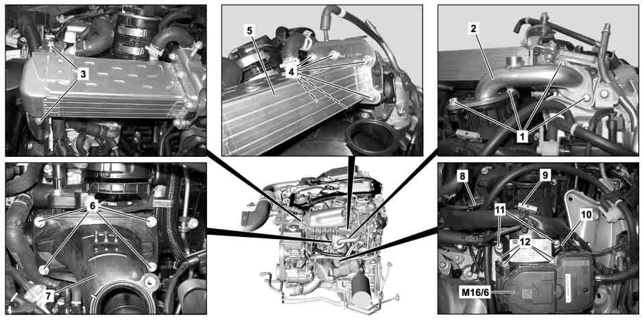
P09.20-2248-09
Shown with model 204.0 |
1 | Screw/bolts | 5 | Exhaust gas recirculation cooler | 9 | Cable bracket | ||
2 | Exhaust gas recirculation line | 6 | Screw/bolts | 11 | Screw/bolts | ||
3 | Screw/bolts | 7 | Mixing chamber | 12 | Screw/bolts | ||
4 | Screw/bolts | 8 | Electrical connection | M16/6 | Throttle valve actuator |

Shown on model 172 |
13 | Refrigerant line |
14 | Screw/bolt |
15 | Retaining clip |
16 | Firewall cover on the left |
P09.20-2308-05
Warning | Risk of injury. Skin or eye injuries may result when handling hot or glowing objects. | Wear protective gloves, protective clothing and safety glasses, if necessary. | |
Topical note | Notes on avoiding damage through contamination and foreign objects | ||
| Remove/install | ||
1 | Remove upper engine cover | ||
2 | Remove firewall cover on the left (16) | Model 172 with engine 651 | |
3 | Remove vacuum reservoir | ||
4 | Remove power steering pump and place aside with lines attached | Engine 651 in model 172 | |
Model 172 with engine 651 | |||
Model 221 with engine 651 | |||
5 | Remove screw/bolts (3, 4), swivel exhaust gas recirculation cooler (5) together with attached coolant lines upwards, place to one side and fix in place | Installation: Replace seal. | |
Bolt, exhaust heat exchanger to valve housing | |||
Bolt, support brace for vacuum reservoir and exhaust heat exchanger to Y-support brace | |||
Bolt, exhaust heat exchanger support to oil filter module | |||
6 | Remove screw/bolts (1) and remove EGR line (2) | Installation: Replace seals. | |
Bolt, exhaust gas recirculation line to charge air distributor | |||
Screw/bolt, exhaust gas recirculation line to valve housing | |||
7 | Remove screw/bolts (6) | Bolt, charge air manifold to charge air distribution line | |
8 | Release and disconnect electrical connection (8) | ||
9 | Remove cable bracket (9) | Installation: Attach cable bracket (9) at the same position again. | |
10 | Remove screw/bolt (14) and retaining clip (15), place refrigerant line (13) to one side | Model 172 with engine 651 | |
To ensure that access to screw/bolts (11) is given. | |||
11 | Remove screw/bolts (12) and place bracket to one side | Bolt, charge air manifold to charge air line | |
12 | Unscrew screw/bolts (11) and take off mixing chamber (7) | Installation: Replace seals. | |
Bolt, charge air manifold to fastening plate | |||
13 | Install in the reverse order |
Henviste dokumenter
- ah0000p500001a Oplysninger om forebyggelse af skader på grund af snavs og fremmedlegemer
- ar0709p0001cd
- ar4630p0500ewi Af- påmontering af servopumpe
- ar4630p0500sx Af- påmontering af servopumpe
- ar4630p0500sxh Af- påmontering af servopumpe
- as0000z000201a Fare for personskade på hud og øjne ved håndtering af varme eller glødende genstande