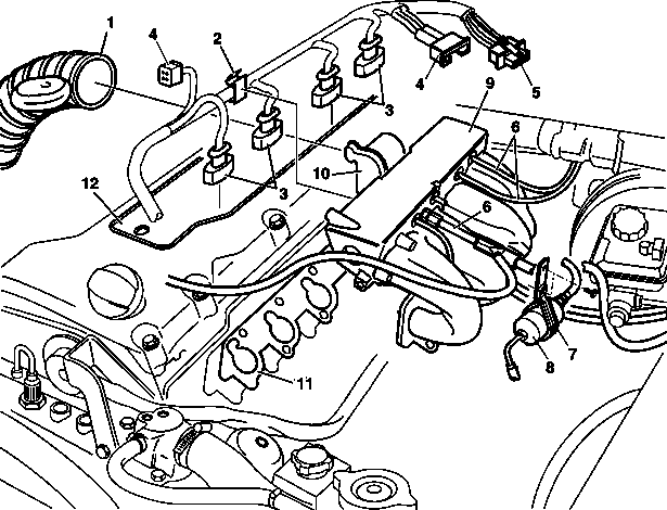
1 | Air intake hose |
2 | Clip |
3 | Injection valve connector |
4 | Gas temperature sensor connector |
5 | Gas pressure sensor connector |
6 | Vacuum line |
7 | Bracket |
8 | Gas filter |
9 | Intake manifold |
10 | Idle speed control actuator |
11 | Intake manifold gasket |
12 | Cylinder head cover trim panel |
13 | Idle speed control connector |
D09.20-0025-06
| Remove/install | ||
1 | Disconnect battery ground line | ||
2 | Remove air intake hose (1) | ||
3 | Remove idle speed control actuator (10) | ||
4 | Unclip the clip (2) from the cylinder head cover and remove the connector (3) from the injection valves on the intake manifold | ||
5 | Remove the connector (4, 5) from the gas temperature and gas pressure sensor | ||
Danger | Risk of death when working on component parts and systems with U >= 30 V alternating voltage (AC) or U >= 60 V direct voltage (DC) | Do not touch damaged or defective live component parts and lines or non-insulated electrical connections and lines. | |
6 | Unplug the connector from the primary side of ignition coils, and run the lines out of the housing of the cylinder head cover | The lines are included with the other lines in a subharness and passed downwards through the intake manifold. | |
7 | Detach vacuum lines (6) from intake manifold | ||
Vacuum line at intake manifold vacuum fitting | |||
8 | Remove intake manifold (9) from cylinder head | ||
Intake manifold to cylinder head | |||
9 | Install in the reverse order |
Henviste dokumenter
- ar0910d8030f
- ar0920d131006d
- ar0920d131007f
- ar3022d1152d
- as0000z003501a Livsfare ved arbejde på komponenter og systemer med U >= 30 V vekselspænding (AC) eller U >= 60 V jævnspænding (DC)