
1 | Shielding |
2 | Soundproofing |
3 | Bolts |
4 | High pressure pump |
5 | Tappet element |
6 | Low pressure pipe |
7 | High pressure pipe |
P07.02-2228-03
Danger | Risk of explosion caused by fuel igniting. Risk of injury to skin and eyes caused by fuel spraying out at high pressure | Keep all ignition sources out of hazard area. | |
Danger | Risk of explosion caused by fuel igniting, risk of poisoning caused by inhaling and swallowing fuel as well as risk of injury to eyes and skin caused by contactwith fuel. | No fires, sparks, open flames or smoking. Pour fuels into suitable and appropriately marked containers only. | |
Topical note | Notes on threaded connections fastened using a tightening angle-based tightening process | ||
Topical note | Notes on avoiding damage through contamination and foreign objects | ||
Note on calculation of tightening torque when using insertion or socket tools with various effective lengths | |||
General information on work on gasoline direct injection system | |||
| Remove | ||
1 | Relieve fuel pressure using diagnostic system. | ||
| Engine 264 in model 238 | ||
| Engine 264 in model 213 | ||
| Engine 264 in model 257 | ||
To do so, select following menu items: | |||
2 | Disconnect ground line from battery. |
| |
Engine 264 in model 213 | |||
Engine 264 in model 257 | |||
3 | Remove rear engine cover. | Engine 264 in model 213, 238, 257 | |
4 | Remove right charge air line. | ||
5 | Remove the charge air cooler and place it at the front with the lines connected. | ||
6 | Rotate engine at crankshaft center bolt in direction of engine rotation to a 79° crank angle (CKA) after top dead center (ignition TDC) on cylinder 1 | Socket wrench bit | |
7 | Remove the cable duct from the cylinder head cover and shielding (1). | ||
8 | Unclip the electrical cable from the shielding (1). | ||
9 | Release and disconnect electrical connection of high-pressure pump (4). | ||
10 | Remove shielding (1). | Tightening procedure for high-pressure pump shielding | |
Loosen the shielding (1) in the direction in contrary to the tightening procedure. | |||
11 | Remove soundproofing (2). | ||
12 | Clean the environment around the high-pressure pump (4), high-pressure line (7), and low-pressure line (6). | Assembly cleaner | |
13 | Release fuel pressure in the fuel high-pressure circuit. | ||
14 | Remove high-pressure line (7) and seal connections with suitable stop plugs. | | |
Box wrench bit | |||
Record plug | |||
15 | Remove the low-pressure line (6) from the cylinder head cover and high-pressure pump (4) and seal the openings using suitable stop plugs. | Box wrench bit | |
Record plug | |||
16 | Remove screw/bolts (3). | | |
17 | Remove high-pressure pump (4). | ||
18 | Remove the tappet element (5) from the cylinder head cover. | ||
| Check | ||
19 | Check the tappet element (5) for wear and damage and replace if necessary. | ||
20 | Check the high-pressure line (7). | ||
Assembly cleaner | |||
If damage is present, | |||
| |||
Replace the high-pressure line (7). | |||
21 | Check low-pressure line (6). | ||
Assembly cleaner | |||
If damage is present, | |||
| |||
Replace low-pressure line (6). | |||
| Clean | ||
22 | Clean mount for high-pressure pump (4) in the cylinder head cover. | Assembly cleaner | |
| Install | ||
23 | Position the tappet element (5) in the cylinder head cover. | | |
24 | Replace sealing ring of the high-pressure pump (4). | ||
25 | Position high-pressure pump (4) in cylinder head cover. | ||
26 | Tighten new bolts (3). | | |
| |||
Bolt, high-pressure pump to cylinder head cover | |||
27 | Install the low-pressure line (6) at the high-pressure pump (4) and cylinder head cover. | Screw, low-pressure line holder to cylinder head/crankcase/holder | |
Union nut, fuel line to high-pressure pump/fuel distributor | |||
Box wrench bit | |||
28 | Install high-pressure line (7). | ||
Union nut, fuel line to high-pressure pump/fuel distributor | |||
Box wrench bit | |||
29 | Install soundproofing (2). | ||
30 | Install shielding (1). | Tightening procedure for high-pressure pump shielding | |
Bolt for high-pressure pump shielding | |||
31 | Install the cable duct at the cylinder head cover and shielding (1). | M61 | |
32 | Clip in the electrical cables at the shielding (1). | ||
33 | Connect electrical connection of high-pressure pump (4) until it is locked. | ||
34 | Install the charge air cooler. | ||
35 | Install right charge air pipe. | ||
36 | Remove the engine cover at the rear. | Engine 264 in model 213, 238, 257 | |
37 | Connect ground line to battery. |
| |
Engine 264 in model 213 | |||
Engine 264 in model 257 | |||
38 | Switch on ignition. | | |
39 | Check the fuel high-pressure circuit. | ||
| Engine 264 in model 238 | ||
| Engine 264 in model 213 | ||
| Engine 264 in model 257 | ||
Warning | Risk of accident from vehicle starting off by itself when engine running. Risk of injury (bruises and burns) resulting from working on the engine while it is being started or when it is running. | Secure vehicle to prevent it from starting off by itself. Wear closed and snug-fitting work clothes. Do not touch hot or rotating parts. | |
40 | Carry out engine test run and check engine for proper operation and leak tightness. | ||
41 | Install engine cover. |


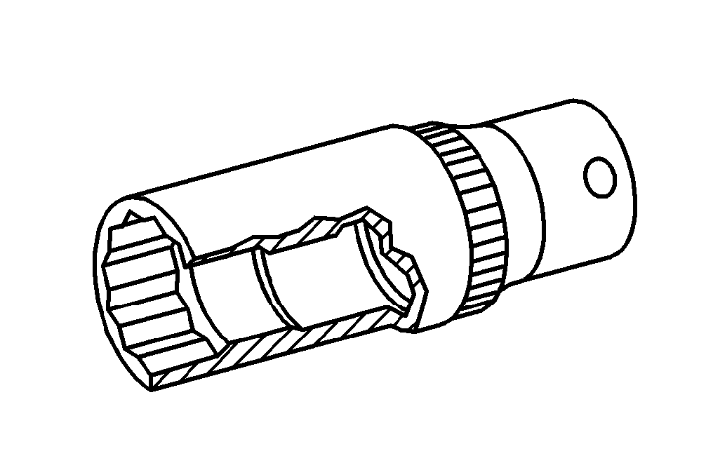
129 589 00 91 00
Record plug
000 589 80 03 00
Box wrench bit
001 589 65 09 00
Socket wrench bit
Henviste dokumenter
- ad0000p200004b
- ad0000p200006fr
- ad0000p200006lwo
- ah0000p001501cw Oplysning om beregning af tilspændingsmoment ved anvendelse af indstiksværktøj eller påsætningsværktøj af forskellig længde
- ah0000p002001a Oplysninger om skrueforbindelser, som er fremstillet efter den drejevinkelstyrede tilspændingsmetode
- ah0000p500001a Oplysninger om forebyggelse af skader på grund af snavs og fremmedlegemer
- ah0700p200001a
- ah0700p200001a Generelle oplysninger om arbejde på direkte benzininsprøjtning
- ar0110p2405mrh
- ar0110p2408mrh
- ar0702p081501mrh
- ar0703p101002mrh
- ar0703p101003mm
- ar0703p101004mm
- ar0703p112001mne
- ar0703p1120mrh
- ar0703p146002mm
- ar0941p6817mrh
- ar5410p0003fr
- ar5410p0003lw Afbrydelse, tilslutning af batteriets stelledning
- ar5410p0003lwo
- as0000z000501a Fare for ulykke ved automatisk igangsætning når motoren kører. Fare for personskade på grund af knusning og forbrænding, hvis der arbejdes mens motoren startes eller kører
- as0716z000101a Fare for eksplosion på grund af antændelse af brændstof. Fare for personskade påhud og øjne på grund af udstrømmende brændstofstråle
- as4700z000101a Fare for eksplosion ved tænding, fare for forgiftning ved indånding og indtagelse af brændstof samt fare for hud- og øjenskader ved kontakt med brændstof