Engine | 900.9 in model 375.1, 970, 972, 975, 976 |
Engine | 902.9 in model 375.1, 970, 972, 974, 975, 976 |
Engine | 902.9 in model 375.3, 950.5/6, 952.5/6, 953.6, 954.5 |
Engine | 902.9 in model 957 |
except code MS8 (Natural gas engine) | |
Engine | 924.9 in model 958.0, 970, 972, 974, 975, 976 |
Engine | 925.9 in model 970, 972, 974 |
Engine | 926.9 in model 950.5/6, 952.5/6, 953.6, 954.5, 957, 958.2 |
Engine | 926.9 in model 958.0 |

Shown on engine 900.9 |
1 | Valve stem seal |
2 | Valve spring |
3 | Retaining clip |
W05.30-1116-06
Warning | Risk of accident from vehicle starting off by itself when engine running. Risk of injury (bruises and burns) resulting from working on the engine while it is being started or when it is running. | Secure vehicle to prevent it from starting off by itself. Wear closed and snug-fitting work clothes. Do not touch hot or rotating parts. | |
Notes on engine oil | |||
Firing order | |||
| Remove | ||
1 | Remove cylinder head cover | ||
2 | Remove charge air manifold | ||
3 | Remove cap of timing case and attach cranking device | ||
Bolt, turning device to timing case | |||
Turning device | |||
4 | Remove soundproofing on top right of frame | ||
5 | Crank engine with turning device until piston for cylinder 1 to be inspected is positioned precisely at ignition TDC | Observe firing order. | |
6 | Remove rocker arm assembly | ||
7 | Remove retaining clip (3) | ||
Replace | |||
8.1 | Remove valve springs (2) from cylinder 1 and 4; replace valve stem seals (1) and install valve springs (2) | Engine 900.9, 924.9 | |
| Exhaust valve spring, exhaust valve and exhaust valve seat ring modified | ||
Magnetic pin | |||
Valve tool case | |||
Pliers | |||
8.2 | Remove valve springs (2) from cylinder 1 and 6; replace valve stem seals (1) and install valve springs (2) | Engine 902.9, 925.9, 926.9 | |
| Exhaust valve spring, exhaust valve and exhaust valve seat ring modified | ||
Magnetic pin | |||
Valve tool case | |||
Pliers | |||
9 | Bring piston on cylinder 2 exactly into the top dead center position | ||
Valve tool case | |||
10.1 | Remove valve springs (2) from cylinder 2 and 3; replace valve stem seals (1) and install valve springs (2) | Engine 900.9, 924.9 | |
| Exhaust valve spring, exhaust valve and exhaust valve seat ring modified | ||
Magnetic pin | |||
Valve tool case | |||
Pliers | |||
10.2 | Remove valve springs (2) from cylinder 2 and 5; replace valve stem seals (1) and install valve springs (2) | Engine 902.9, 925.9, 926.9 | |
| Exhaust valve spring, exhaust valve and exhaust valve seat ring modified | ||
Magnetic pin | |||
Valve tool case | |||
Pliers | |||
11 | Bring piston on cylinder 3 exactly into the top dead center position | Only for engine 902.9, 925.9, 926.9. | |
Valve tool case | |||
12 | Remove valve springs (2) from cylinder 3 and 4; replace valve stem seals (1) and install valve springs (2) | Only for engine 902.9, 925.9, 926.9. | |
| Exhaust valve spring, exhaust valve and exhaust valve seat ring modified | ||
Magnetic pin | |||
Valve tool case | |||
Pliers | |||
| Install | ||
13 | Install retaining clip (3) | Bolt connecting retaining clip of nozzle holder combination to cylinder head | |
14 | Install rocker arm assembly | ||
Only install cylinder head cover after valve clearance has been adjusted. | |||
15 | Set valve clearance | ||
| Model 375, 950, 952, 953, 954, 957, 970, 972, 974, 975, 976 | ||
Model 958 | |||
16 | Install charge air manifold | ||
17 | Install cylinder head cover | ||
18 | Install soundproofing on frame above on the right | ||
19 | Remove cranking device at timing case and attach cap | ||
Inspection hole cap to timing case | |||
Turning device | |||
20 | Check engine oil level at display; correct if necessary | Observe engine oil quality set in maintenance system or Specifications for Operating Fluids. | |
21 | Start engine and allow to run in idle for 10 s until the oil pressure has built up, then run the engine at varying speeds | ||
22 | Switch off engine and check for leaktightness | Visual inspection. |
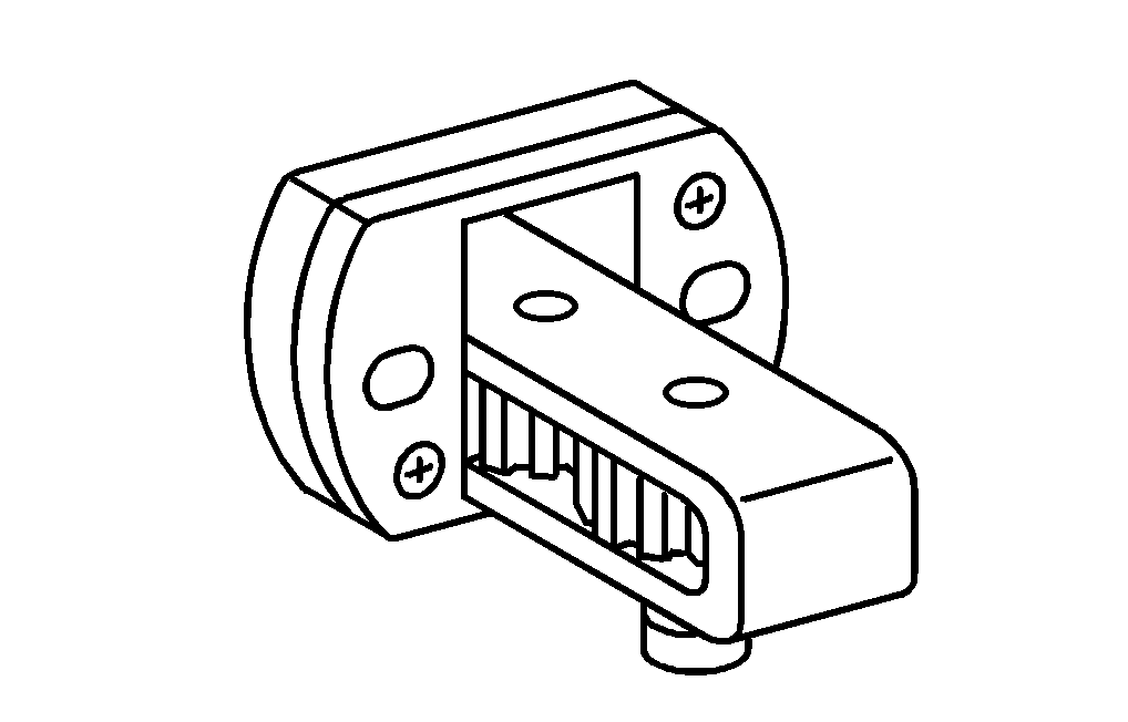


904 589 04 63 00
Turning device
210 589 00 40 00
Magnetic pin
541 589 00 61 00
Valve tool case
606 589 00 37 00
Pliers
Henviste dokumenter
- ah0100n010001aa Tændingsrækkefølge
- ah1800n010101ha Oplysninger om motorolie
- ap0530w0560b Indstilling af ventiltolerance
- ar0120w5014j
- ar0310w704103j
- ar0330w160003j
- ar0500w5521j
- ar0530w351201j
- ar0941w8681j
- as0000z000501a Fare for ulykke ved automatisk igangsætning når motoren kører. Fare for personskade på grund af knusning og forbrænding, hvis der arbejdes mens motoren startes eller kører
- bt0530n000401rh