
P05.20-2126-05
Shown on engine 271.9
1 Positioning pin
2 Holding device
3 Camshaft adjuster

P05.20-2336-08
Shown on engine 271.8
3 Camshaft adjuster
1 Positioning pin
| Remove/install | ||
1 | Remove cylinder head cover | ||
2 | Remove front cover from cylinder head | ||
3 | Crank engine at center bolt for the crankshaft in direction of rotation until piston of cylinder 1 is positioned at ignition TDC | The TDC marking on belt pulley/ vibration damper must be aligned with positioning edge on timing case cover. Cams for the intake and exhaust camshaft at cylinder 1 must be positioned upright at an angle. | |
Installation: Inspect basic position of camshafts. | |||
| |||
4 | Mount retainer (2) | Mount retainer (2) over cutouts in the camshaft housing-top section. | |
| |||
5.1 | Release timing chain | Engine 271.9 | |
| |||
5.2 | Remove chain tensioner | Engine 271.8 | |
Installation: Install new chain tensioner. | |||
6 | Remove center bolt and remove camshaft adjuster (3) | At the same time unhinge timing chain and secure against falling down. The direction of loosening for center bolt on intake or exhaust camshaft is the same (see arrow). | |
7 | Installation: Camshaft adjusters (3) do not require any particular adjustment as they feature a positioning pin (1). To avoid confusion, the camshaft adjusters (3) are marked with "A" for exhaust camshaft and with "E" for intake camshaft. | ||
Engine 271.8 | |||
| |||
8 | Install in the reverse order |
Camshaft, camshaft adjustment
Number | Designation | Engine | Engine | ||
BA05.20-P-1002-02A | Center bolt, camshaft adjuster to camshaft | Stage 1 | Nm | 130 | 90 |
Stage 2 | ° | - | - | ||


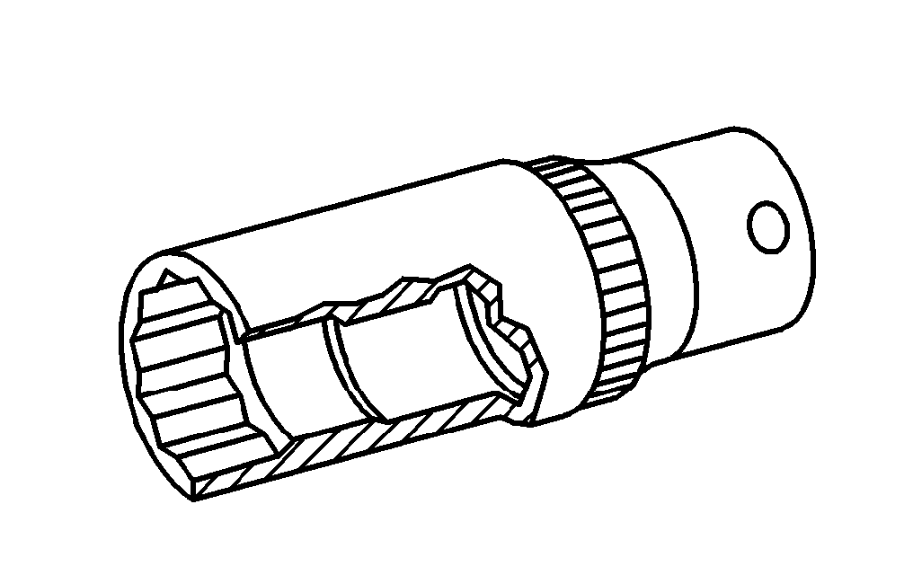

271 589 00 31 00
Wrench socket
Wedge
Holding device
Wrench socket
271 589 00 61 00
001 589 65 09 00
271 589 00 10 00