
1 | Screw |
2 | Screw |
3 | Coolant line |
4 | Coolant line |
5 | Coolant line |
6 | Poly-V-belt |
7 | Belt pulley/vibration damper |
8 | Bolts |
W03.30-1130-06

7 | Belt pulley/vibration damper |
10 | Bolts |
11 | Bracket |
13 | Bolts |
W03.30-1170-11

7 | Belt pulley/vibration damper |
9 | Flange for propeller shaft |
10 | Bolts |
11 | Bracket |
12 | Bolts |
W03.00-1003-12
Warning | Risk of injury caused by pinching or crushing when working on springs or spring bodies that are under tension | Use only approved tensioning devices; additionally screen off hazardous area if necessary. Check special tools for damage and proper operation (visual inspection). Wear protective gloves. | |
Warning | Risk of injury caused by body parts being pinched or crushed as cab is tilted | Ensure that no one is within the tilting range of the cab as it is being tilted. Always tilt the cab all the way to the end position and secure it with the safety strut. | |
Topical note | Notes on threaded connections fastened using a tightening angle-based tightening process | ||
Topical note | Notes on tilting the cab | ||
| Remove/install | ||
1 | Tilt cab. | ||
2 | Remove noise encapsulation. | ||
3 | Remove screw/bolts (1, 2). | ||
4 | Fasten coolant lines (3, 4) with a cable tie on the coolant line (5). | ||
5 | Attach cranking device to the flywheel housing and block the flywheel with the turning device. | ||
Bolt, TDC inspection hole cap to flywheel housing | |||
Bolt, turning device to flywheel housing | |||
Turning device | |||
6 | Remove propeller shaft. |
| |
Screw/bolt, fan drive propeller shaft to front fan bearing | |||
Screw/bolt, fan drive propeller shaft to vibration damper | |||
7 | Slacken tension on poly-V belt (6) and remove from belt pulley/vibration damper (7). | ||
| Damage profiles for a poly-V belt | ||
Routing diagram | |||
Installation: Check poly-V belt (6) for good condition. | |||
If damage is present, | |||
| |||
Install new poly-V-belt (6). | |||
8 | Unscrew screws (10, 13) and remove bracket (11). | Only for model 956 as of vehicle identification end number 247410 | |
9 | Unscrew screws (12) and remove the rear flange for propeller shaft (9). | Only for model 956 as of vehicle identification end number 247410 | |
Screw/bolt, fan drive propeller shaft to vibration damper | |||
10 | Unscrew screw/bolts (8) for belt pulley/vibration damper (7). | Installation: Moisten thread of screw/bolts (8) with engine oil. | |
Bolt, vibration damper to crankshaft | |||
11 | Remove belt pulley/vibration damper (7). | ||
12 | Measure length of bolts (8). | ||
Bolt, vibration damper to crankshaft | |||
If permissible shank length is exceeded: | |||
| |||
replace screws (8). | |||
13 | Install in the reverse order |
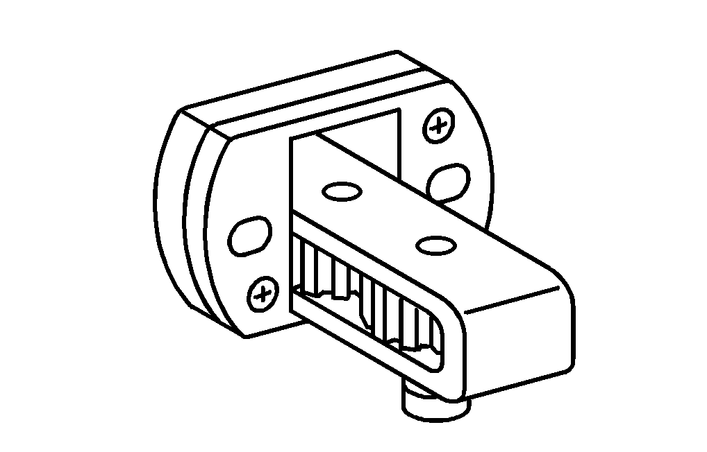
904 589 04 63 00
Turning device
Henviste dokumenter
- ah0000p002001a Oplysninger om skrueforbindelser, som er fremstillet efter den drejevinkelstyrede tilspændingsmetode
- ah6080n000301a Oplysninger om tipning af førerhus
- ap1322d135101a Skadesbilleder for kilerem
- ar0330w160003md
- ar0330w160008md
- ar1320w100001md
- ar1322w390205md
- ar2040w562401ng
- as0000z000101a Fare for kvæstelse på grund af fastklemning og knusning ved arbejde på fjedre eller fjederlegemer, som er under forspænding
- as6080z000101a Fare for personskade ved fastklemning og knusning, når førerhuset tippes