F. Model 201
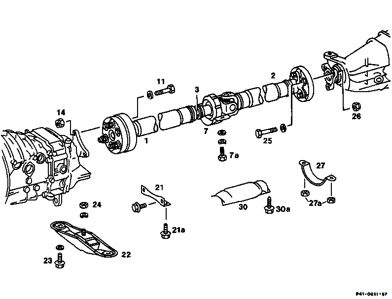
P41-0011-57
Exhaust shielding plate (30) | screw off and on (item 1). |
Transmission | lift, support, lower. |
Engine carrier (22) | screw off and on, 45 Nm (item 3). |
Starting 09/88 bracket (27) | screw off and on (item 4). |
Propeller shaft clamping nut (3) | loosen for approx. two turns, |
Front propeller shaft (1) | remove from and mount on transmission, |
Rear propeller shaft (2) | remove from and mount on rear axle, 45 Nm. |
Propeller shaft intermediate bearing (7) | screw off and on. Tighten hex. head screws (7a) only after fastening propeller shaft to transmission and rear axle, 25 Nm (item 9). |
Propeller shaft, complete | force off centering pin on transmission and rear axle and pull out toward the rear. |
Centering sleeves | check for wear, with bronze bushings, grease cavities with Molykote grease and use multi-purpose grease with multi-component bearing bushings (refer to Specifications for Service Products page 266.2 and 267, quantity per sleeve approx. 6 g). |


Special tools

Removal and installation
-------------------------------
1 Unscrew exhaust shielding plate (arrows).
149-24597

2 Lift transmission and support.
3 Unscrew hex. head screws and hex. nut (arrows) and remove rear engine carrier with engine mount.
Installation note
Tightening torque 45 Nm.
141-24593

4 Unscrew bracket (27) for fastening seat belt on vehicles starting 09/88.
Installation note
Tightening torque of hexagon nuts 280 Nm.
141-36561

5 Unscrew cross-bridge (21) if installed from
tunnel.
Installation note
Tightening torque 25 Nm.
101-33951/2

6 Loosen propeller shaft clamping nut for approx. two turns without sliding back rubber sleeve (sliding along).
Open-end wrench element 201 589 00 01 00.
Installation note
Tightening torque 30 - 40 Nm, while paying attention to correct seat of rubber sleeve.
Layout with single-pipe exhaust system
141-24596

Layout with double-pipe exhaust system
0135-36249

7 Remove front propeller shaft from transmission.
Note
Flexible coupling remains on propeller shaft.
Installation note
Renew self-locking hex. nuts, tightening torque 45 Nm.
141-24590
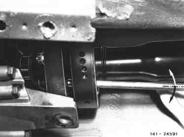
8 Prior to sliding back propeller shaft, loosen
fitted sleeves of soft pull-push flexible coupling
installed on transmission end by means of a
mandrel in the joint flange. For this purpose, use
a cylindrical mandrel of 10 mm dia. and approx.
150 mm in length.
141-24591

9 Remove propeller shaft from rear axle.
Note
Flexible coupling remains on propeller shaft.
Installation note
Renew self-locking hex. nuts (arrows), tightening torque 45 Nm.
141-24594

10 Unscrew hex. head screws (7a) of propeller shaft intermediate bearing on frame floor.
Installation note
Tighten hex. head screws only after fastening
propeller shaft on transmission and rear axle,
tightening torque 25 Nm.
127-24376/1
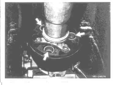
Note
On vehicles with manual transmission, after tightening transmission propeller shaft connection, pay attention to correct seat of rollers in vibration damper and force in rollers, if required (arrows).
141-24674

11 Force propeller shaft from centering pin on transmission and rear axle and remove toward the rear.
141-24592

If a separation of the propeller shaft is required, reassemble the parts again as shown. The front propeller shaft is provided with a hump and the flexible fork of the rear propeller shaft with two arrow-type humps (arrows). The hump of the front propeller shaft should be located between the two arrows on the flexible fork (arrows).
141-23660

12 Check flexible couplings, centering sleeves, vibration damper and propeller shaft intermediate bearing for wear and renew parts if required.
Note
A soft pull-push (tangential) flexible coupling or a hard flexible coupling is installed on transmission end. Special attention should be paid to damage particularly in area of vulcanized fitted sleeves in the case of the soft pull-push flexible coupling.
A Soft pull-push flexible coupling front model 201
B Rear flexible coupling model 201 and model 201.034/035 front and rear
141-26418

13 If during renewal of flexible coupling the vibration damper is separated from propeller shaft, mount vibration damper and three-legged flange as shown.
The installation position is correct when the arrow on vibration damper is mounted behind hump on three-legged flange. (Model 201 with a bolt circle diameter of 80 mm).
141-29238

Layout model 201 with 80 mm bolt circle dia.
1 Front propeller shaft
10 Centering sleeve
11 Hex. socket screw
12 Flexible coupling
12b Centering bushing
13 Washer
14 Self-locking hex. nut
18 Universal flange
20 Vibration damper
1413-10977

14 Model 201 with a bolt circle diameter
of 90 mm.
The installation position is correct when the arrow of vibration damper (20) is pointing toward hump on three-legged flange.
Marking on 1st version up to 12/89
P41-2001-13

Marking on 2nd version as of 01/90
1 Front propeller shaft
20 Vibration damper
P41-2042-13

Layout model 201 with 90 mm bolt circle diameter
1 Front propeller shaft
10 Centering sleeve
11 Hex. head screw
12 Flexible coupling
12c Stop washers
13 Washer
14 Self-locking hex. nut
18 Universal flange
20 Vibration damper
1414-12712
15 With bronze bushing, grease cavities of both
centering sleeves with Molykote grease and use
multi-purpose grease with multi-component
bearing bushings (refer to Specifications for
Service Products page 266.2 and 267, filling
capacity per sleeve approx. 6 g).
16 For installation proceed vice versa.
Odkazované dokumenty
- bb0040p026602a Dlouhodobé mazací tuky (třída NLGI 2)
- bb0040p026700a Víceúčelové tuky (třída NLGI 2)
- ra4100107pr00x
- ra4100107ta00x