07.1-195 Testing exhaust gas recirculation
A. Engine 601.911/912 up to 01/93,
Engine 602, 603

Function diagram exhaust gas recirculation
1) not applicable on engine 601 code 960 and 830 model year 1991
136 | Starter ring gear |
180 | Thermovalve (black) opens at 40 °C |
224 | Accelerator pedal |
B6 | Hall-effect speed sensor 1) |
L3 | Starter ring gear speed sensor |
N37/2 | Exhaust gas recirculation (ARF) control unit |
S25/1 | 100 °C temperature switch |
S25/7 | 25 °C temperature switch, ARF |
S25/9 | 97 °C temperature switch |
S27/6 | Microswitch, compressor cut-off/ARF |
Y27 | Exhaust gas recirculation (ARF) switch-over valve |
Y28 | Pressure control flap switch-over valve |
a | Fresh air to vehicle interior |
b | Other consumers |
1 | Injection pump |
2 | Governor |
4 | PLA unit |
5 | ADA unit |
6 | Vacuum unit (stop) |
60 | Exhaust gas recirculation (ARF) valve |
61a | Throttle, blue |
61b | Throttle, orange |
62 | Filter |
65 | Vacuum control valve |
67 | Vacuum pump |
72 | Damper |
94 | Air guide housing |
100 | Vacuum unit |
105 | Intake manifold |
110 | Exhaust manifold |
120 | Exhaust gas recirculation line |
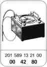
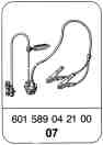
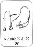
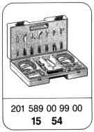
Special tool
Commercially available tools
Digital tester | e. g. Bosch, MOT 001.03 |
e. g. Sun, DIT 9000 | |
Multimeter | e. g. Sun, DMM-5 |
Note
Use Y-distributor, part no. 117 078 01 45 for vacuum tester.
Test condition
Coolant temperature 60-80 °C.
Function test


Checking ARF valve (60) with engine switched off
Apply vacuum of approx. 300 mbar to ARF valve. Pull off vacuum line.
ARF valve closes audibly.
ARF valve fails to close.
Renew ARF valve.
End of test
Test vacuum transducer (123) and vacuum setting (only for automatic transmission). Connect vacuum tester with Y distributor to connection "ARF" and read off vacuum level at idling speed.
Specifications in mbar:
Pneumatic pressure control flap up to 1988
32020
35020 only
Mechanical pressure control flap as of 1989
30020
If the vacuum is above or below specification, adjust vacuum. To do this, remove protective cap (124) and adjust with socket wrench insert (4 mm) to specified value.
Settings in mbar:
Pneumatic pressure control flap up to 1988
3205
3505
as of model year 1986 must no longer be ajusted
Mechanical pressure control flap as of 1989 engine 601.91, 602.91
3005
Engine 603.91
3505

Check supply vacuum on connection "VAC", renew vacuum transducer if required. Check vacuum lines according to function diagram.
Check supply vacuum on vacuum pump (07.1-160).
Set value: > 700 mbar
End of test
Checking vacuum control
Connect vacuum tester with Y-distributor to ARF valve (60). Check vacuum values and position of vacuum unit (100) and vacuum control flap.
Test values in order.
Test values not in order.
Vacuum ok
Vacuum not ok
1/min | ARF valve mbar | Vacuum control flap position |
Leerlauf | 0 | open |
1000 50 | 150 - 360 | closed |
2500 50 | 150 - 360 | closed |
3000 50 | 0 | open |


Check vacuum supply and individual parts.
End of test
Function in order.
Function not in order.
Check individual parts.
Checking microswitch (S27/6, I + II)
Connect vacuum tester with Y-distributor to EGR valve (60).
Run engine at 100050/min.
Actuate microswitch (S27/6 I), the vacuum on the ARF valve (60) drops to 0 mbar. The vacuum control flap (in the air guide housing) returns to basic position.
Actuate microswitch (S27/6 II), the vacuum control flap (100) returns to basic position.
Piston rod of vacuum unit retracted - vacuum control flap closed (arrow).
Testing components
-------------------------------

Remove ARF valve and apply vacuum of approx. 300 mbar with vacuum tester.
ARF valve lifts approx. 4 or 6 mm off the seat (end stop arrow).
Pull off vacuum line, the ARF valve should close audibly.
If one of these test steps is not successful, renew ARF valve.
Checking ARF valve (60) with engine switched off
Apply vacuum of approx. 300 mbar to ARF valve. Pull off vacuum line.
ARF valve closes audibly.
ARF valve fails to close.
A open
B closed
End of test


Check vacuum lines according to function diagram.
Check supply vacuum at vacuum pump.
Set value: > 700 mbar
Adjust vacuum control valve (65)
(07.1-170).
End of test
Checking vacuum control valve (65)
A. Automatic transmission:
Connect vacuum tester with Y-distributor to "VCV" connection of vacuum transducer (123) and check vacuum at idle speed.
Set values:
At idle speed > 300 mbar
With engine switched off and control linkage in full load stop position 0 mbar.
B. Manual transmission: (except USA)
Connect vacuum tester with Y-distributor to connection "A" of change-over valve (Y27) and check vacuum.
Set values:
At idle speed > 300 mbar
With engine switched off and control linkage in full-load stop position 0 - 250 mbar.
Test values in order.
Test values not in order.

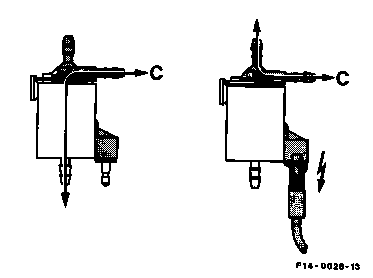
Checking change-over valves (Y27 and Y28)
Connect voltmeter to connector of change-over valve and read voltage at 100050/min.
Set value: approx. 12 V.
Voltage in order.
Voltage not in order.
End of test
Check electrical actuation according to wiring diagram, renew ARF control unit (N37 or N37/2) if required.
Connect vacuum tester with Y-distributor to connection "C" and check vacuum at 1000 or 120050/min, a voltage of 12 V is present.
Engine 601.911/912, 602 up to model year 1985
Change-over valve (Y27) 35020 mbar
Change-over valve (Y28) > 700 mbar
Engines 601.9, 602, 603
at 100050/min, a voltage of 12 V is present.
Change-over valve (Y27) 250 - 400 mbar
Change-over valve (Y28) 250 - 400 mbar
From model year 1990 check engines with
mechanical actuation of the pressure control
flap at 100050/min, applying 12V.
Change-over valve (Y27) 350 - 400 mbar
Change-over valve (Y28) > 700 mbar

Check supply vacuum at the vacuum pump (07.1-160).
Set value > 700 mbar.
Check vacuum lines according to function diagram.
End of test
Engines with mechanical actuation of vacuum control flap as of model year 1990.
Check vacuum at the straight connection of the thermovalve (180) and supply vacuum to the vacuum pump.
Set value: > 700 mbar
Check vacuum line in accordance with the functional diagram, renew thermovalve (180).
Vacuum value not in order.
Vacuum value in order.


1) Measured at 20 °C ambient temperature. (The resistance changes by 4% for each 10 °C change in ambient temperature).
Checking speed signal
Remove plug connector (L3X). Connect multimeter and press button "V". Allow engine to idle.
Display: > 1.5 V
Voltage rises with increasing speed.
In order.
Not in order.
End of test
Remove starter ring gear speed sensor (L3).
Connect multimeter as above and press key
"W". Check resistance.
In order.
Not in order.
Renew starter ring gear speed sensor (L3).
End of test
Display: "Beru" 530 1) W 10%
"VDO" 1900 1) W 10%
Inspect starter ring gear speed sensor (L3) for accumulation of dirt or metal chips, clean if required.


Checking activation of temperature
switches
(S25/9) 97 °C Engine 602
Engine 603
(S25/1) 100 °C Engine 601
Function in order, renew temperature switch.
Function not in order
Check electrical activation, renew ARF control unit (N37 or N37/2) if required.
End of test
Connect vacuum tester with Y-distributor to
ARF valve.
Run engine at 1000/min. Pull plug off
temperature switch (S25/1) and bridge, except
1-pole version of temperature switch (S25/1),
hold the plug against ground (electronic clutch
should be heard to attract).
Vacuum 0 mbar on ARF valve.

Checking activation of 25 °C temperature
switch (S25/7)
Function in order.
Function not in order.
Check electrical activation, renew ARF control unit (N37 or N37/2) if required.
End of test
Connect vacuum tester with Y-distributor to ARF valve.
Engine temperature > 25 °C
Run engine at 1000/min, pull plug off
temperature switch and hold against ground.
Vacuum 0 mbar on ARF valve.


Checking microswitch (S27/6 I and II)
Engine switched off. Pull coupling off
microswitch (S27/6) and check with ohmmeter
for continuity on plug 2 and 4 and 1 and 3.
At idle speed: 0 W
At full load: W
Display in order.
Display not in order.
Renew microswitch (S27/6).
End of test.
Checking full-load contact on microswitch (S27/6 I)
Display in order.
Display not in order.
Renew microswitch (S27/6).
End of test.
Engine switched off. Coupling pulled off
microswitch (S27/6). With ohmmeter check
continuity on plug 1 and 5.
At idle speed: W
At full throttle: 0 W
Vehicles with manual transmission in model 201.122 with engine 601.921


Check electrical activation of change-over valve (Y27). Connect multimeter to plug (arrow) of change-over valve (Y27) and again test- drive.
If voltage (approx. 12 V) is available at a speed > 788 km/h, check electrical activation of change-over valve (Y27) according to wiring diagram.
Renew defective parts if required.
If no voltage is present, renew change-over valve (Y27).
End of test.
Checking speed shut-off
Connect vacuum tester with Y-distributor to ARF valve. Run vehicle on test stand or road in the 5th gear under part load.
Read off vacuum.
Display
speed
< 788 km/h: approx. 300 mbar
> 788 km/h: approx. 0 mbar
Vacuum values in order.
Vacuum values not in order.