03-7041 Removing and installing pistons
Preceding work: Cylinder head removed (01-5800). Oil pump removed (18-6023). |
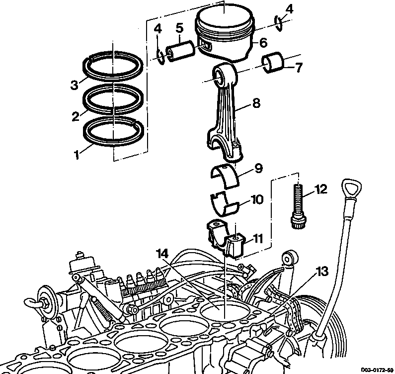
8 | Conrod |
9 | Conrod bearing shell (top) |
10 | Conrod bearing shell (bottom) |
11 | Conrod bearing cap |
12 | Conrod bolts 30 Nm+90° |
13 | Crankcase |
14 | Cylinder bore |
1 | Bevel ring |
2 | Taper face ring |
3 | Rectangular ring |
4 | Snap rings replace |
5 | Piston pin |
6 | Piston |
7 | Conrod bush check, replace if necessary. |
Data
Piston clearance in mm | maximum 0.12 |
Distance from piston crown in TDC position to crankcase contact surface in mm | 0.735 0.965 |
Conrod bush diameter (A) in mm | 26.012 26.018 |
Peak-to-valley height of conrod bush | Rz 5 |
Conrod bolt dimensions
Thread | M 91 |
Stretch shaft diameter (C) when new in mm | 7.4 - 0.1 |
Minimum stretch shaft diameter (C) in mm | 7.1 |
Length (L) when new in mm | 52 - 0.3 |
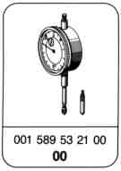


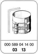
Special tools
Note On engines OM 601 as of engine no. 601940 10 164357 and on engines OM 602 as of engine no. 602940 10 164085 it is only permissible to install Alcan pistons with lead-coated piston stem or Mahle pistons with graphited piston stem. Mahle pistons without graphited piston stem as new parts must not be installed with modified cylinder head bolts (recognizable from the two opposite ribs on the bolt head). |
Used Mahle pistons without graphited piston stem may be installed with modified cylinder head bolts (recognizable from the two opposite ribs on the bolt head). Pistons of repair size 1 with a diameter of D=89.7 mm may be installed with the previous or modified cylinder head bolts (recognizable from the two opposite ribs on the bolt head). |

Removing
-------------------------------
1 Remove combustion residues from the respective cylinder bore.
2 Unscrew conrod bolts (12) and take off conrod bearing cap (11).

3 Remove conrod bearing shells (9 and 10).

4 Press piston (6) up together with conrod (8) and take out.

5 Remove snap rings (4) and press out piston pin (5).
6 Take piston (6) off the conrod (8).
Installing
-------------------------------
1 Examine conrod bush; replace, if necessary.
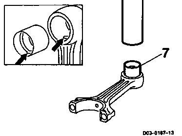
2 Replacing conrod bush:
2.1 Fit on new conrod bush (7) and press in.
Note
The oil drillings in the conrod boss and in the new conrod bush must be aligned.
The old conrod bush is pressed out by the new one.

2.2 Ream conrod bush to size (A).
A=26.012 - 26.018 mm with Rz=5.

3 Fit piston (6) onto the conrod (8) so that the arrow (15) and the locking slot (16) are facing in direction of travel.

4 Oil piston pin (5) and press in by hand.
Note
Do not heat piston.
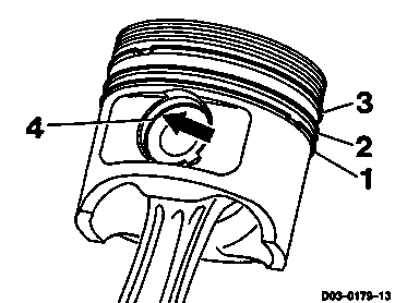
5 Place new snap rings (4) into the grooves (arrow).
6 Examine piston rings (1, 2 and 3); replace, if necessary.
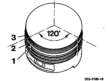
7 Position joints of piston rings (1, 2 and 3) evenly around circumference of piston.
8 Oil cylinder bore, conrod bearing journals, conrod bearing shells and pistons.
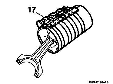
9 Fit on tensioning strap (17) and compress piston rings.
17 000 589 04 14 00
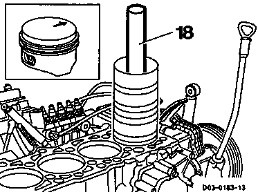
10 Fit piston together with conrod and tensioning strap onto the cylinder bore.
11 Push piston into the cylinder with a wooden block (18).
Note
The arrow in the piston crown must be facing in direction of travel.

12 Insert conrod bearing shells (9 and 10).
Note
Do not mix up top and bottom conrod bearing shells.
13 Fit on conrod bearing cap (11) so that the retaining lugs are on the same side of the conrod bearing (arrows).
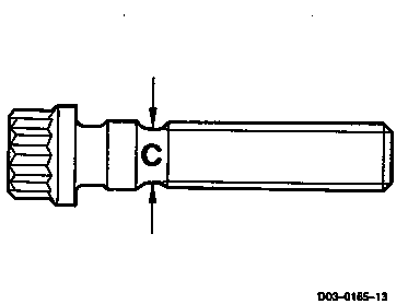
14 Measure stretch shaft diameter (C) of the conrod bolts.
Limit:
C=7.1 mm.
If the measurement obtained is less, the conrod bolt should be replaced.

15 Oil conrod bolts (12) and screw tight,
30 Nm + 90 ° angle of rotation.
Note
Do not use a bending-rod torque wrench for the angle of rotation torque.
16 Rotate crankshaft and examine clearance between conrod and crankshaft.
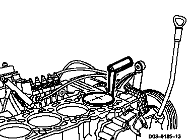
17 Examine clearance at piston crown in direction of piston pin between piston and cylinder.
Limit:
Maximum clearance = 0.12 mm.
If the reading obtained is greater, the cylinder bore should be widened to the next repair size (01-9291) and an oversize piston installed or a cylinder liner and a standard size piston installed.

18 Position piston to TDC and measure the distance between piston crown and contact surface of crankcase at points marked (arrows).
Specifications:
Maximum distance = 0.965 mm.
000 589 53 21 00
363 589 02 21 00
366 589 00 21 05
If the measurement obtained is greater, the crankcase should be replaced.