01-040 Crankcase Ventilation - Function
Operation No. of operation texts and operation values or standard texts and flat rates |
A. Engines 102.922/924 (with Stromberg carburetor)

P01-0075-57
A | Fresh air |
B | Blowby gases |
109 | Oil separator |
200 | Water separator |
201 | Intake manifold (bypass bore dia. 1.5 mm) |
Function
-------------------------------
The engine blowby gases flow through the oil separator (109) at the cylinder head cover and a pipeline to the water separator (200) in the air filter (clean air side).
The oil separated out in the oil separator (109) flows back through a passage (dia. 3 mm) to the cylinder head.
The blowby gases are drawn out of the water separator (200) depending on the intake manifold vacuum through a bypass passage (dia. 1.5 mm) in the intake manifold (201) and pass together with the intake air into the combustion chambers.
Coolant-heated crankcase breather,
except
-------------------------------
Since 02/88 a coolant-heated crankcase breather has been fitted to these engines. This prevents the crankcase breather from freezing up.
Standard implementation
Model | Engine | Engine End No. | |
Manual | Automatic | ||
124.020 | 102.922 | 057460 | 023121 |
124.080 | |||
201.023 | 102.924 | 042627 | 010640 |
The coolant-heated crankcase breather can also be retrofitted to models with the Stromberg carburetor manufactured prior to this date.

Scope of operation
-------------------------------
1 Drain coolant (20-010).
2 Remove air filter (09-410).
3 Remove heating water hose (134a) between intake manifold and starter cover.
P09-2049-13

4 Assemble coolant-heated crankcase breather as shown in illustration.
P09-2040-13

5 Install coolant-heated crankcase breather as shown in illustration.
6 Pour in coolant (20-010).
Check whether the heated vent line (103) becomes warm (test with hand).
P09-2038-13

7 Install air filter (09-410).
Shorten hose (135) between shaped hose
(Y distributor 136) and liquid separator in air
filter (111) to 210 - 215 mm. Fit onto the plastic
tube (137) without kinks and free of tension.
P09-2039-13
Operation text and flat rate
-------------------------------
All models Retrofitting coolant-heated crankcase breather.
02-0918/01 Basic operation
02-0919/01 Related operation
Parts
Designation | Part No. |
Vent line | 102 090 10 32 |
Vent hose Models 123, 124 | 102 094 06 87 |
Vent hose Model 201 | 102 094 03 87 |
Shaped hose (supply) | 102 203 25 82 |
Shaped hose (return) | 102 203 24 82 |
or according to consumption |
|
Plastic tube (length 30 mm and 170 mm) | 008 997 60 82 |
Shaped hose (Y distributor) | 102 078 19 81 |
Hose clip (3 off) | 916 026 014 000 |
Available from: Plant 50 (Sindelfingen)
B. Engines 102.922/924 (with 2 E-E carburetor)
These engines have a coolant-heated engine breather.

P01-0186-35
|
Function ------------------------------ The blowby gases of the engine flow out of the crankcase to the oil separator at the cylinder head cover. The oil separated out flows through a passage (dia. 3 mm) in the oil separator back to the cylinder head. The blowby gases pass from the oil separator, depending on the load condition of the engine (intake manifold vacuum), into the combustion chamber along the following paths: At idling or deceleration (high intake manifold vacuum) |
At the same time, clean air is drawn Part and full load range (low intake manifold vacuum) |
To prevent the vent line freezing up (103a) at low outside temperatures, it is heated by the coolant. The heating line (106) is integrated in the vent line (103a) and connected via the heating hose (104) to the intake manifold heater. The coolant flows back to the coolant pump (1) along the return lines (109b and 133) and the distributor piece (131).
No water separator is fitted in the air filter of these engines (engines with Stromberg carburetor have a water separator) because the blowby gases and the condensate contained in the gases passes along the shortest path from the cylinder head cover to the combustion chambers in the frequently driven part load range, and water therefore can no longer settle in the lines of the crankcase ventilation.
C. Engines 102.962/963/982/985 (CIS-E injection)
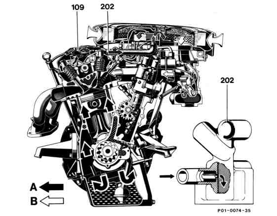
109 Oil separator
202 Idle air distributor
(bypass passage dia.
1.5 mm)
A Fresh air
B Blowby gases
P01-0074-35
Function
-------------------------------
The engine blowby gases flow through the oil separator (109) at the cylinder head cover and through a pipeline to the idle air distributor (202) or to the air filter (clean air side).
The oil separated out in the oil separator (109) flows back through a passage (dia. 3 mm) to the cylinder head.
At a high intake manifold vacuum, the blowby gases are drawn through the bypass passage (dia. 1.5 mm) in the idle air distributor (202) and the idle air passage in the intake manifold and flow to the combustion chambers. At the same time, a small quantity of clean air from the air filter is drawn in as well through the bypass passage.
At a low or no intake manifold vacuum, the blowby gases flow to the clean air side in the air filter and pass together with the intake air to the combustion chambers.