Overview
This document contains information on:
General
Function requirements
Function
General
The process of mixture preparation involves conveying the liquid fuel through the high-pressure fuel circuit, controlling the injection and forming the mixture. The liquid fuel is delivered via the high-pressure fuel circuit to the fuel injection system. The mixture is formed (i. e. the vaporized fuel is blended with the supplied air) in the combustion chamber.
Function requirements
Engine management ON (terminal 87M)
Engine in operation
Function
Lambda control (diesel engine)
The diesel engine operates with a heterogeneous, internal mixture and self-ignition. The air–fuel ratio λ specifies the extent to which the actual air–fuel mix deviates from the stoichiometric fuel–air ratio in the cylinder. The lambda values for diesel engines are between λ=1.15 and λ=2.0 at full load and between λ=10 and λ=18 in idling.
Lambda control (gasoline engine)
Direct-injection gasoline engines work in stratified-charge and homogeneous operation. In homogeneous operation, the lambda values are between λ=0.5 and λ=1.3; in stratified-charge operation, the lambda values depend on the driving and load condition (e. g. partial or full-load operation).
Gasoline direct injection involves a process of forming a mixture in which the gasoline is injected at high pressure directly into the combustion chamber.
High-pressure fuel circuit
The high-pressure fuel circuit essentially comprises the following components:
Fuel distributor
High-pressure lines
Pressure limiting valve (diesel engine)
Fuel pressure sensor in fuel distributor
Fuel injectors
Quantity control valve
High-pressure fuel pump
The high-pressure fuel pump connects a low-pressure fuel circuit and a high-pressure fuel circuit. The task of the high-pressure fuel pump is to compress the fuel and pump it into the fuel distributor.
The quantity control valve in the high-pressure fuel pump controls the fuel flow into the high-pressure fuel circuit.
From the fuel distributor, the fuel is conveyed via high-pressure lines to the fuel injectors, which inject the fuel directly into the combustion chamber, selectively for each cylinder and finely atomized. On the basis of a characteristics map, the combustion engine control unit calculates the injection for the current operating condition. The injection quantity depends o the fuel pressure in the fuel distributor and the activation duration of the fuel injectors.
The fuel pressure in the fuel distributor is controlled by the quantity control valve. The fuel pressure in the fuel distributor is measured by the fuel pressure sensor and limited by the pressure limiting valve (diesel engine).
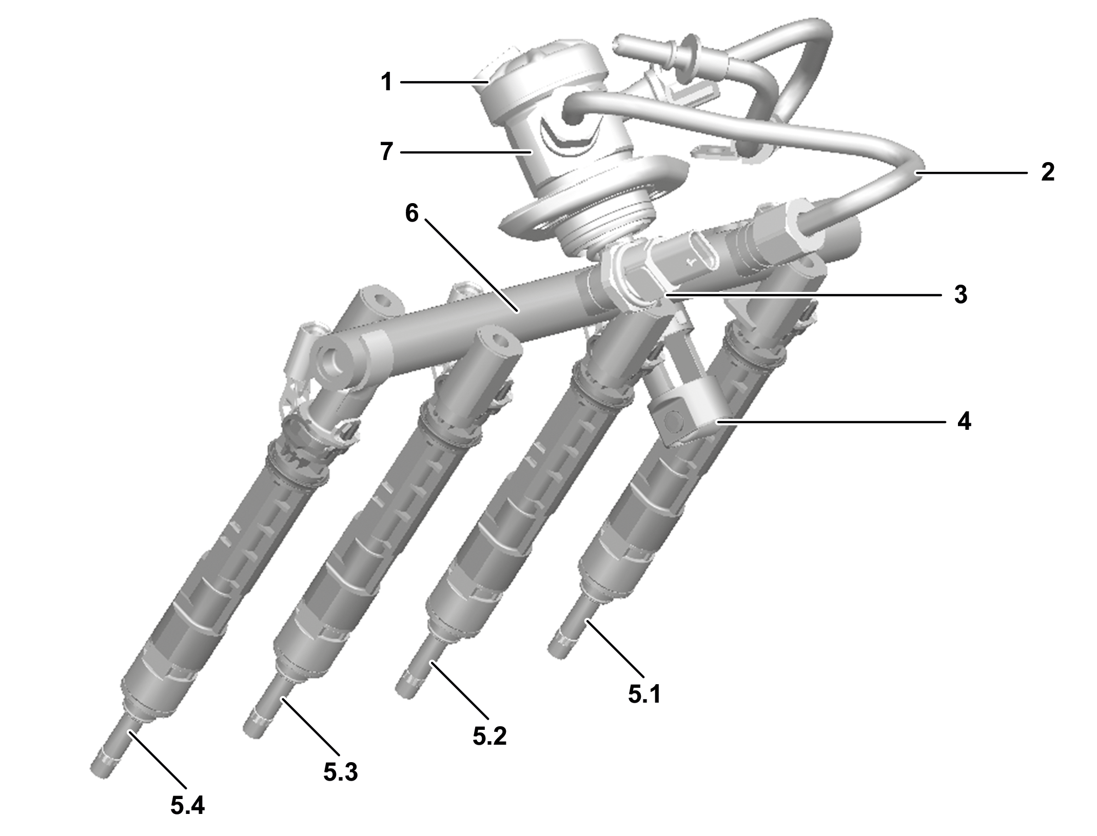
Example illustration of high-pressure fuel circuit on 4-cylinder spark-ignition engine |
1 | Quantity control valve |
2 | High pressure pipe |
3 | Fuel pressure sensor |
4 | Roller tappet |
5.1 | Cylinder 1 fuel injector |
5.2 | Cylinder 2 fuel injector |
5.3 | Cylinder 3 fuel injector |
5.4 | Cylinder 4 fuel injector |
6 | Fuel distributor |
7 | High-pressure fuel pump |
P07.00-A001-76
Gasoline engine injection control
Direct-injection gasoline engines are designed for homogeneous and heterogeneous combustion. The fuel injection pressure can be as high as 250 bar. The injectors are piezo-controlled multi-hole valves, which are usually located centrally in the combustion chamber. The high-pressure fuel pump is driven by the camshaft.
The following operating conditions are supported by multi-point injection:
Start
Heating the three-way catalytic converter
Combustion stabilization at high engine speed, i.e. engine speed < 2000 rpm
Keeping the three-way catalytic converter warm over prolonged idling phases
With the help of a characteristics map, the combustion engine control unit calculates the injection duration and pressure on the basis of the following signals:
Fuel pressure and temperature
Hall signal from the intake camshaft
Hall signal from the outlet camshaft
Coolant temperature
Charge air temperature upstream of the throttle valve
Charge air temperature downstream of the throttle valve
Pressure downstream of the throttle valve, engine load
Engine loading request
Accelerator pedal sensor, accelerator pedal actuation (fast or slow)
Engine speed
Lambda value upstream of the catalytic converter
The requirements of the torque coordination function are also taken into account.
The combustion engine control unit controls the injection duration under the following operating conditions:
Partial load operation
Full load operation
Load change
During the injection period (i.e. when the injector is open), the injection quantity is fed to the injector.
Partial load operation
In partial-load operation, when the engine is warm, the combustion engine control unit calculates the activation time of the fuel injectors as a function of the following factors:
Lambda control
Fuel pressure
Requested engine torque
Full load operation
In full-load operation, when the throttle valve is fully open, the combustion engine control unit extends the actuation time of the fuel injectors and increases the injection pressure in order to ensure maximum engine torque.
At the accelerator pedal sensor, about 10 to 90 % slewing range is defined as partial load and more than about 90 % slewing range is defined as wide open throttle.
Load change
If the position of the accelerator pedal changes suddenly (e. g. when the vehicle accelerates), the throttle valve is opened or closed at high speed. This can cause momentary thinning or enrichment of the air–fuel mix. The combustion engine control unit adjusts the air–fuel mix accordingly by extending or shortening the activation time of the fuel injectors on the basis of the characteristics map. This prevents any juddering caused by the rapid opening/closing of the throttle valve.
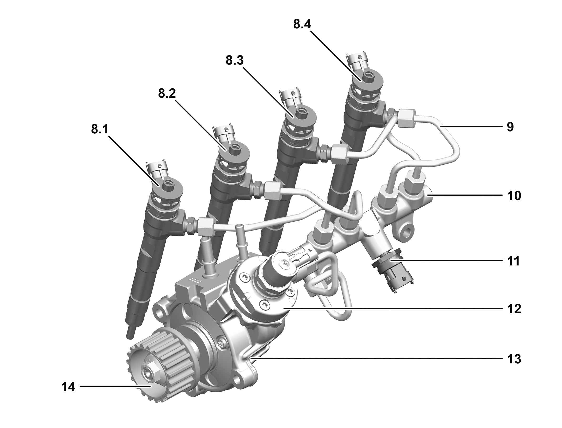
Example illustration of high-pressure fuel circuit on 4-cylinder diesel engine |
8.1 | Cylinder 1 fuel injector |
8.2 | Cylinder 2 fuel injector |
8.3 | Cylinder 3 fuel injector |
8.4 | Cylinder 4 fuel injector |
9 | High-pressure lines |
10 | Fuel distributor |
11 | High-pressure fuel pressure sensor |
12 | Quantity control valve |
13 | High-pressure fuel pump |
14 | Gear |
P07.00-A000-76
Diesel engine injection control
In diesel engines, up to six injections per working cycle are possible for precision combustion control. The maximum injection pressure can be as high as 2000 bar.
To reduce combustion noise, double preinjection takes place in the large characteristics map range. Postinjection takes place to optimize emissions.
During regeneration of the diesel particulate filter, multiple timed postinjections take place.
The combustion engine control unit supplies the required fuel quantity to the engine on the basis of the load condition and coolant temperature.
The injection control is described in the following steps:
Fuel pressure control
Preinjection
Main injection
Postinjection
Injection quantity correction
Fuel pressure control
Fuel pressure control is performed through quantity control by means of the quantity control valve at the high-pressure fuel pump.
Preinjection
To reduce combustion noise and exhaust emissions, the main injection is preceded by a preinjection, which makes the combustion process more smooth.
Main injection
The main injection is performed following preinjection and generates power and torque. The main injection is controlled by the injection time and injection duration.
Postinjection
The postinjection not only helps to increase the exhaust temperature, but also supports the process of converting the exhaust components in the oxidation catalytic converter and particulate filter regeneration. The increased exhaust temperature subsequently burns the soot particles in the exhaust gas.
Injection quantity correction
Injection quantity correction additionally has the following requirements:
Engine speed between 1000 rpm and 2600 rpm, i. e. overrun mode or standard driving mode
Engine oil temperature > 80 °C
Injection quantity correction is subdivided into subareas:
Zero quantity calibration
Main injection quantity correction
Zero quantity calibration
The friction that occurs when the fuel injectors are opened/closed means that the injection quantity changes over the duration. The changed injection quantity can be corrected by adjusting the activation duration. During normal engine operation or in overrun mode, a pilot injection quantity is calibrated at defined intervals selectively for each cylinder. This actuation duration corresponds to a defined injection quantity. The difference between the new and nominal activation duration is used as a basis for correcting the injection quantities.
Main injection quantity correction
For this function, the main injection quantity is corrected using the oxygen sensor upstream of the catalytic converter. Here, the injection quantity is adjusted until the target lambda value stored in the combustion engine control unit is reached.
The emission values are influenced owing to the tolerances of the fuel injectors and hot film mass air flow sensor. To keep the emission values constant, the combustion engine control unit changes the exhaust gas recirculation rate via the low-pressure exhaust gas recirculation actuator and the high-pressure exhaust gas recirculation actuator. The residual oxygen content is monitored over the oxygen sensor element upstream of catalytic converter.
Safety fuel shutoff
To ensure traffic and occupant safety, the safety fuel shutoff system is activated under certain conditions.
The combustion engine Control unit activates the safety fuel shutoff system under the following conditions:
Direct or indirect crash signal
Mechanical failure in the throttle valve actuator (in gasoline engines)
Direct or indirect crash signal
If the combustion engine control unit receives a direct or indirect crash signal from the SRS control unit, it switches off the fuel pump and the quantity control valve. To depressurize the fuel system, the fuel injectors are also briefly activated.
Mechanical failure in the throttle valve actuator (in gasoline engines)
The combustion engine control unit continuously compares the target and actual position of the throttle valve actuator. If any deviation (i.e. mechanical failure) is identified, the fuel supply is shut off.
Function schematics | |||
Function schematic for safety fuel shutoff | Engine 260, 282, 608 in model 118, 177, 247Engine 264 in model 167 | ||
Engine 176, 177 in model 167 | |||
Engine 139 in model 118, 177 | |||
Engine 654 in model 118, 167, 177, 247Engine 654 in model 213, 238, 257 as of model year 2021Engine 656 in model 167, 223 | |||
Engine 254, 264 in model 213, 238, 257 as of model year 2021Engine 256 in model 167Engine 256 in model 213, 238 as of model year 2021 | |||
Engine 256 in model 223 | |||
Engine 176 in model 223 | |||
Function schematic for injection control | Engine 608 in model 118, 177, 247 | ||
Engine 282 in model 118, 177, 247 | |||
Engine 260 in model 118, 177, 247Engine 264 in model 167 | |||
Engine 654 in model 118, 167, 177, 247Engine 654 in model 213, 238, 257 as of model year 2021Engine 656 in model 167, 223 | |||
Engine 254, 264 in model 213, 238, 257 as of model year 2021Engine 256 in model 167Engine 256 in model 213, 238 as of model year 2021 | |||
Engine 176, 177 in model 167 | |||
Engine 139 in model 118 | |||
Engine 256 in model 223 | |||
Engine 176 in model 223 | |||
Engine 279 in model 223 | |||
Additional basic functions | |||
Lambda control, basic function | Engine 139, 176, 177, 254, 256, 260, 264, 279, 282 | ||
Control units | |||
Combustion engine control unit, basic function | Engine all (CAR) | ||
Components | |||
Fuel high-pressure pump, basic function | Engine all (CAR) | ||
Fuel injectors, basic function | Engine all (CAR) | ||
Fuel distributor fuel pressure sensor, basic function | Engine 282, 608 | ||
Quantity control valve, basic function | Engine all (CAR) | ||
Throttle valve actuator, basic function | Engine all (CAR) |