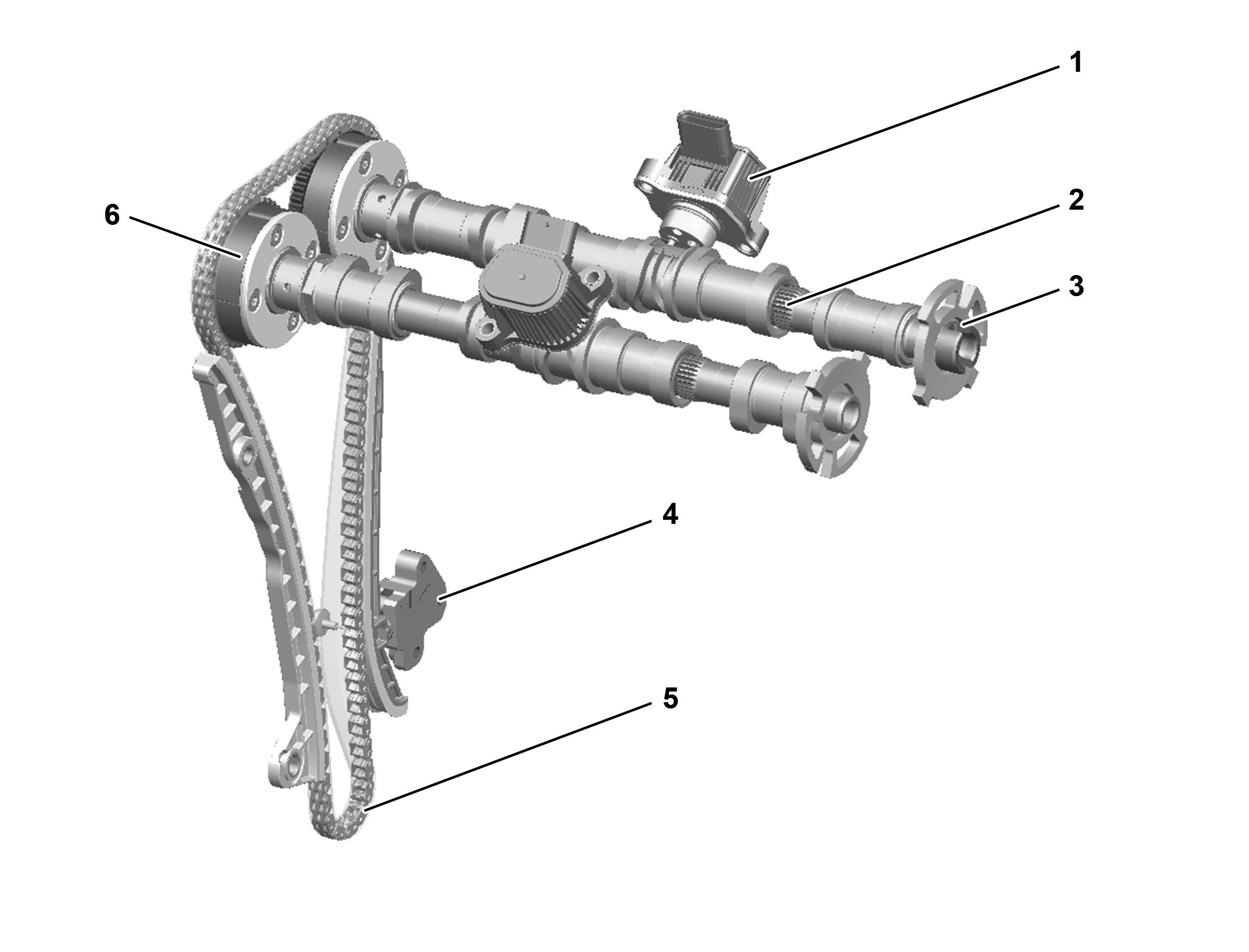
Valve assembly |
1 | Valve lift switchover actuator |
2 | Camshaft sleeve intake side |
3 | Pulse wheel |
4 | Chain tensioner |
5 | Timing chain |
6 | Camshaft positioner |
P05.00-A006-76
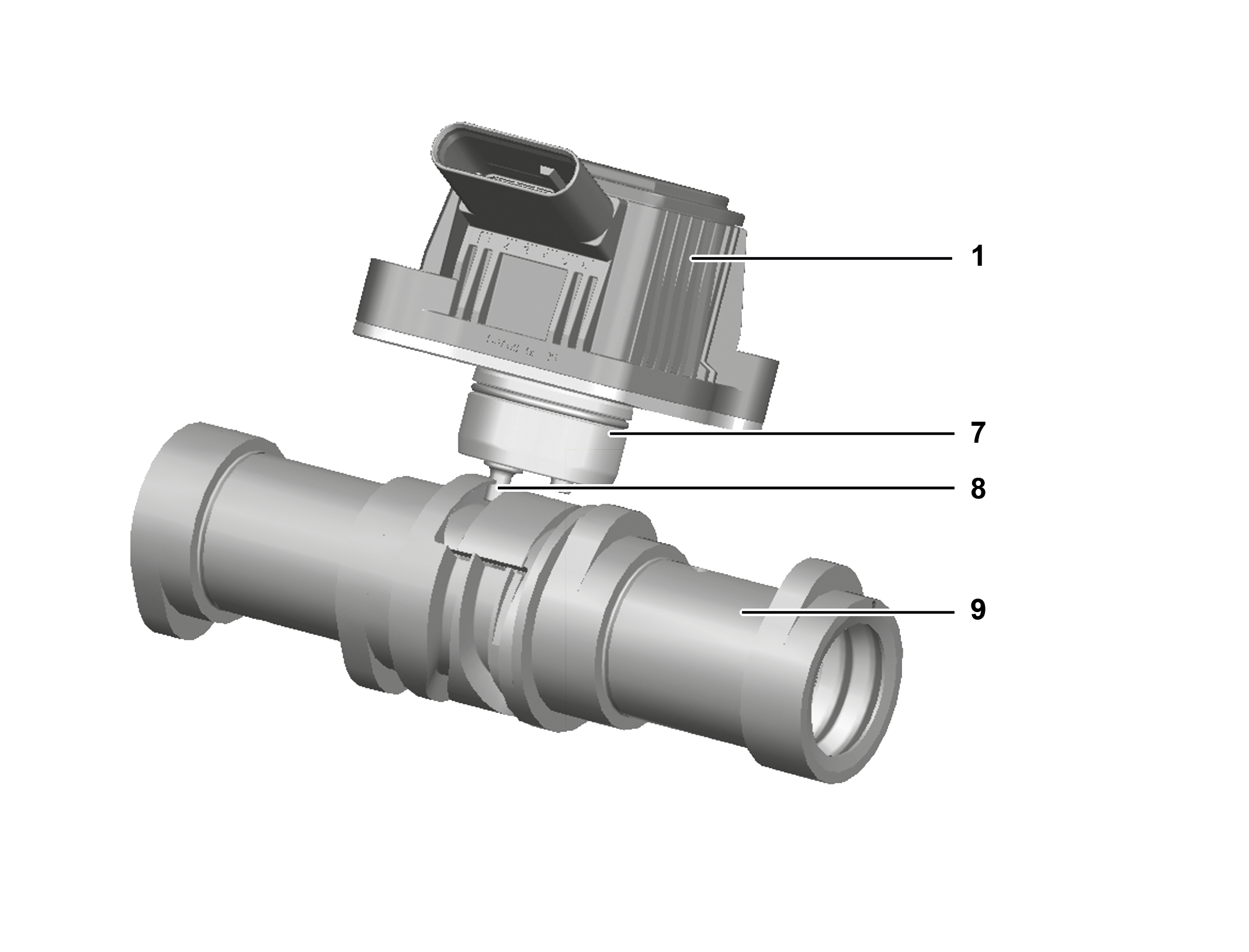
Valve lift switchover actuator |
1 | Valve lift switchover actuator |
7 | Actuator |
8 | Actuator pin |
9 | Camshaft sleeve |
P05.00-A007-76
Overview
This document contains information on:
General
Function requirements
Function
General
The engine timing takes place based on a camshaft adjustment and a valve lift switchover in the form of a cylinder deactivation. The cylinder deactivation takes place in the partial-load range and enables variable control of the valve lift. This leads to an optimization of the engine output and a reduction of charge change losses and pollutants. The engine design with 120 kW output has cylinder deactivation, which enables "dynamic downsizing". In order to provide an operating energy input that is still sufficient, cylinders 2 and 3 can thus be shut off in the low load and engine speed range.
Function requirements
Engine management ON (circuit 87M)
Engine in operation
Function
Camshaft adjustment
A camshaft positioner adjusts the intake and exhaust camshafts to "early" and "retarded". This means the valve overlap in the event of a gas exchange can be varied within wide limits. As a result, the engine torque characteristics and exhaust characteristics improve. The smallest valve overlap during gas exchange arises if the exhaust camshaft is adjusted to the maximum BTDC (advanced) and the intake camshaft to the maximum ATDC (retarded). The resulting increased fresh gas content produces more engine torque and engine output.
The intake camshaft adjustment solenoid and the exhaust camshaft adjustment solenoid are actuated by the combustion engine control unit with a pulse width modulated signal. The control plungers are adjusted via the characteristics map-dependent duty cycle. The oil flows for the camshaft positioner are controlled according to its position. In the camshaft positioners, the oil turns the vane pistons, which are firmly connected to the camshafts.
Cylinder shutoff
The cylinder deactivation additionally has the following function requirements:
Rpm range: 1,250 – 4,000 rpm
Active for at least 3 s
ECO start/stop function active
The cylinder deactivation takes place on the intake and exhaust side via the associated camshafts on cylinders 2 and 3 using a map-controlled valve lift switchover. For the valve lift, there is a two-stage adjustment. When the switchover to the "zero lift" cam takes place, roller-type rocker arms travel in this position in a 360° base circle and the valves remain closed. The second lift position is the regular "full-lift" cam for operation as a multi-cylinder engine, as happens at cylinders 1 and 4.
An electromagnetic actuator with two actuator pins controls an axial displacement of the camshaft pieces on the intake and exhaust camshaft. The shift gates are located in the center between the movable camshaft pieces. The actuator is actuated in a characteristics-map-dependent manner with a pulse width modulated signal. To activate the cylinder deactivation, a coil is energized in the actuator, and the respective actuator pin enters a corresponding curved track on the camshaft piece. With the rotation of the camshaft and the design of the curved track, the camshaft pieces are moved axially, and the respective cam acts on the intake valves. An incline in the curved track then results in the actuator pin being returned to the start position. To deactivate the cylinder deactivation, a second actuator pin enters the adjacent curved track and the reset of the camshaft to the other valve lift takes place accordingly. As a result, the cylinder deactivation takes place through just one actuator per camshaft in each case (intake actuator of cylinders 2 and 3, exhaust actuator of cylinders 2 and 3). The position determination of the actuator pins takes place via an integrated Hall sensor in the actuator.
The cylinder deactivation takes place depending on the input factors "engine speed", "load", and "temperature". The dethrottling of cylinders 2 and 3 leads to a reduction of fuel consumption. At the same time, compared to multi-cylinder engine operation, the load point of active cylinders 1 and 4 moves to higher loads. As a result, clear efficiency advantages and, therefore, fuel savings occur through reduced charge change losses in particular.