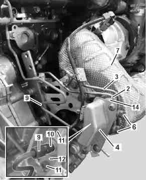
2 | Coolant pipes |
3 | Coolant pipes |
4 | Case upper part |
6 | Bolts |
7 | Exhaust pipe |
9 | Fuel tubes |
10 | Injector nozzle |
11 | Bolts |
12 | Case lower part |
14 | Cooling adapter |
B49.20-0020-02

10 | Injector nozzle |
12 | Case lower part |
13 | Sealing ring |
14 | Cooling adapter |
15 | Sealing ring |
16 | Screening cylinder |
W49.20-1120-11
Warning | Risk of injury. Skin or eye injuries may result when handling hot or glowing objects. | Wear protective gloves, protective clothing and safety glasses, if necessary. | |
Danger | Risk of explosion caused by fuel igniting, risk of poisoning caused by inhaling and swallowing fuel as well as risk of injury to eyes and skin caused by contactwith fuel. | No fires, sparks, open flames or smoking. Pour fuels into suitable and appropriately marked containers only. | |
Warning | Risk of accident from vehicle starting off by itself when engine running. Risk of injury (bruises and burns) resulting from working on the engine while it is being started or when it is running. | Secure vehicle to prevent it from starting off by itself. Wear closed and snug-fitting work clothes. Do not touch hot or rotating parts. | |
Warning | Risk of injury to skin and eyes suffering scalding from contact with hot coolantspray. Risk of poisoning from swallowing coolant. | Do not open cooling system unless coolant temperature is below 90 °C. Open cap slowly and release the pressure. Do not pour coolant into beverage containers. | |
Topical note | Notes on self-locking nuts and bolts | ||
Topical note | Notes on avoiding damage through contamination and foreign objects | ||
Topical note | Notes on coolant | ||
| Remove/install | ||
1 | Open the engine compartment | The access to perform maintenance and repair works varies according to the manufacturer and the body type. | |
2 | Remove the acoustic encapsulation | Installation: Reinstall the anti-noise capsule only after performing the leak-tightness test. | |
3 | Drain the coolant in the radiator of the engine | ||
4 | Disconnect battery ground cable | ||
5 | Unscrew the hollow screws (6) | ||
6 | Remove the coolant lines (2, 3) | Installation: Replace sealing rings. | |
Hollow screw of coolant line on nozzle unit or crankcase | |||
Screw of the coolant line flange on turbo pressure positioner | |||
7 | Remove the case upper part (4) | Screw of the housing upper part in the lower part of nozzle unit housing | |
8 | Remove the fuel line (9) at the injection nozzle (10) | Brace the injection nozzle (10). | |
Fastening nut of fuel line on injector nozzle | |||
9 | Loosen the screws (11) and remove the case lower part (12) | Installation: Clean the case lower part (12). Replace the sealing ring (13). | |
Cooling adapter of injection nozzle with the housing lower part on exhaust gas pipe | |||
10 | Remove the cooling adapter (14) at the exhaust pipe (7) | Installation: Clean the sealing surfaces on the cooling adapter (14) and on the exhaust pipe (7). | |
11 | Remove the sealing ring (15) and the screening cylinder (16) with sealing | Installation: Replace the sealing ring (15) and the screening cylinder (16) with sealing. | |
12 | Remove the injection nozzle (14) at the cooling adapter (10) | Only when the injection nozzle (10) or the cooling adapter (14) are replaced. | |
Injection nozzle on cooling adapter | |||
13 | Install in reverse order | ||
14 | Start the engine and perform the engine test cycle | Let engine running at higher speed. | |
15 | Check the area around the DPF regeneration injection unit for leak tightness, then, turn off the engine | Visual inspection. | |
16 | Carry out the purging routine with the diagnosis device | ||
The procedure is completely menu-guided. |
Odkazované dokumenty
- ah0000n000101a Upozornění k samopojistným šroubům a maticím
- ah0000n500001h Upozornění k zamezení poškozením kvůli znečistění a výskytu cizích těles
- ah2000n208001a Upozornění ke chladicí kapalině
- ar2000b1142evi
- ar4920b1051evi
- ar5410b0003evi
- as0000z000201a Nebezpečí poranění kůže nebo očí při zacházení s horkými nebo žhavými předměty
- as0000z000501a Nebezpečí úrazu při samovolném rozjetí vozidla při běžícím motoru. Nebezpečí poranění pohmožděním a popálením při výkonech prováděných během startování nebo při běžícím motoru
- as2000z000101a Nebezpečí poranění kůže a očí opařením vystřikující, horkou chladicí kapalinou. Nebezpečí otravy při požití chladicí kapaliny
- as4700z000101a Nebezpečí výbuchu při vznícení, nebezpečí otravy při vdechnutí a požití paliva inebezpečí úrazu v důsledku přímého doteku kůže a očí s palivem