Repair materials
Number | Designation | Order number |
BR00.45-Z-1001-06A | Long-life grease | A 000 989 63 51 |

T68.30-0025-01
1 Remove cover (1).
The ALB plate is on the rear side of the cover (1).

T42.80-0007-11
2 Read off lever length (l) on ALB plate and note down.
3 In accordance with the determined rear axle load, read off the rear axle exit pressure (p) and the lever travel (f) on the ALB plate and note down.
Example:
Assumed rear axle load: 2400 kg
p: 2.9 bar
f: 39 mm
l: 75 mm

T42.80-0008-11
4 Check as from which rear axle load the maximum braking pressure is specified for the first time, along with the relevant lever travel (a).
Example:
Maximum brake pressure: 8.2 bar
The maximum brake pressure is reached for the first time at a rear axle load of 6150 kg:
Relevant lever travel (a): 18 mm
5 Calculate and note down check path "s":
Check path = Lever travel for determined rear axle load minus lever travel when maximum brake pressure reached for first time
s = f - a
Example:
s = 39 mm - 18 mm = 21 mm

T42.80-0009-02
6 Check lever length (l) on lever (2).
If the lever length (l) does not match the details on the ALB plate, undo bolt (3), adjust lever length (l) and tighten bolt (3) again.
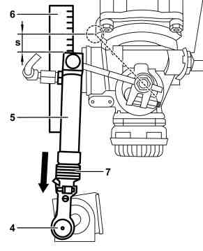
7 Remove ball head (4) from lower linkage (arrow).
8 Press and hold brake pedal.
The ALB controller should now have an entry pressure of min. 8.5 bar applied to it.

T42.80-0010-02
9 Slowly shift the compressed air cylinder (5) upwards until the maximum brake pressure is applied to the combination cylinder.
Example:
Maximum brake pressure: 8.2 bar
10 Position a straightedge (6) and shift the compressed air cylinder (5) downwards by the calculated lever travel (s).
Example:
Calculated lever travel (s): 21 mm
T42.80-0011-02
11 Grease ball head (4) and mount, without changing the lever position of the ALB controller. If necessary, adjust the compressed air cylinder (5).
Adjust compressed air cylinder (5):
Detach boot (7) and jam nut concealed below it. Repeat operation steps 8 to 10. Turn ball head (4) until it can be mounted onto the lower linkage, without altering the lever position of the ALB controller. Finally, tighten the jam nut and
fasten boot (7) in place using new cable tie.