ar4020b032209ta

Checking and adjusting caster

Typ ar · téma 40.20 · verze 0500 · 2019-07-05

Platí pro: Model 958.0/1 with front axle 733.894/895 Model 958.184/186 with front axle 733.861 Model 958.2/4 with front axle 739.392 Model 958.20/25 with front axle 739.390 Model 958.260/264 with front axle 739.391 Model 958.43/44/45/46 with front axle 739.390 Model 958.471/472/478 with front axle 739.391 Model 958.472 with front axle 739.412

Není k dispozici v jazyce „cs“; zobrazeno v jazyce Angličtina.

Zařazení

Funkční skupina 2 Podvozek › 40 Kola, měření geometrie podvozku › 40.20 Měření geometrie podvozku — Řada 958 (modely 0**, 1**, 184, 186, 2**, 20*, 25*, 260, 264, 4**, 43*, 44*, 45*, 46*, 471, 472, 478)

EinPAS 20 Podvozek › 20.10 Měření podvozku › 20.10.20 Diagnostika/zkouška/proměření/nastavení — Řada 958 (modely 0**, 1**, 184, 186, 2**, 20*, 25*, 260, 264, 4**, 43*, 44*, 45*, 46*, 471, 472, 478)

Platí také pro motory/převodovky: 733 861, 733 894, 733 895, 739 390, 739 391, 739 392, 739 412

AR40.20-B-0322-09TA

Checking and adjusting caster

Model

958.0/1 with front axle 733.894/895

Model

958.184/186 with front axle 733.861

Model

958.2/4 with front axle 739.392

Model

958.20/25 with front axle 739.390

Model

958.260/264 with front axle 739.391

Model

958.43/44/45/46 with front axle 739.390

Model

958.471/472/478 with front axle 739.391

Model

958.472 with front axle 739.412

Modification notes

18.06.2019

Caster

BE40.20-B-1003-11G

25.06.2019

Cáster

BE40.20-B-1003-11G

Steering geometry

Number

Designation

Vehicles 934.2, 938.1, 958.2/4 with front axle 739.392

Vehicles 958.184/186 with front axle 733.861

BE40.20-B-1003-11G

Caster

°

1,30° (30')

1,30° (30')

Steering geometry

Number

Designation

Vehicles 958.20/43 4X2 with front axle 739.390

Vehicles 958.25/44/46 6X2 with front axle 739.390

BE40.20-B-1003-11G

Caster

°

2°28' (30')

1,30° (30')

Steering geometry

Number

Designation

Vehicles 958.45 6X4 with front axle 739.390

Vehicles 958.260/264 6X4 with front axle 739.391

BE40.20-B-1003-11G

Caster

°

1,30° (30')

2° (30')

Steering geometry

Number

Designation

Vehicle 958.472 6X4 with front axle 739.412

Vehicles 958.471/472/478 6X4 with front axle 739.391

BE40.20-B-1003-11G

Caster

°

1,30° (30')

1,30° (30')

Steering geometry

Number

Designation

Vehicles 958.03/07/09 with front axle 733.894/895

BE40.20-B-1003-11G

Caster

°

1,30° (30')

Checking and adjusting caster

Check
The illustration shows adjustment of the 1st front axle. Adjustment procedure for the 2nd front axle is analogous.

1

Position the projector (5) on the projector support (4).


2

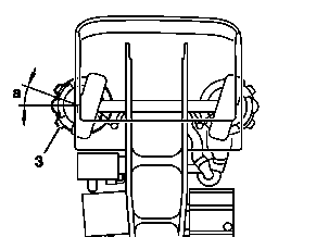
Turn the wheel to the right on the rotating plate (3) by angle (a).


a = 20°


3

Put the projector (5) in the horizontal in the longitudinal direction and tighten the wing screw (16).


4

Turn the rotating button (29) until level (30) is centered.


W40.20-0034-01

W40.20-0032-01

Checking and adjusting caster

5

Place the scaled disc (32) in position 0 for later measurement.


6

Turn the wheel to the right on the rotating plate (3) by angle (a).


a = 20°


W40.20-0036-01

W40.20-0035-01

Checking and adjusting caster

7

Place the projector in the horizontal position.


8

Turn the rotating button (29) until level (30) is centered.


9

Read the value indicated on the scale disc for caster measurement (32) (e.g.: 4°).


The scaled disc for caster measurement (32) is divided in measuring sections "positive caster" and "negative caster". The "positive caster" measuring range is 0 to +15°. The "negative caster" measuring range is 0 to -3°. One division on the scaled disc represents 10'.


10

Record the measuring value on the alignment form.. 


11

If these values are not reached, adjust caster.


12

Repeat the same procedure for work steps 1 to 11 on the other wheel of the 2nd font axle.


W40.20-0037-01

Checking and adjusting caster

Adjust

13

Support the axle to prevent falling.


14

Remove spring clamps (6).


15

Lift and support the chassis frame.


16

Remove wedge (7) and install the selected wedge.


The wedges are available in several angles


17

Lower the chassis frame, making sure the pin fits correctly into the hole of the wedge.


18

Install spring clamps (6).


Replace self-locking nuts (8).


19

Repeat the caster check.


W32.20-1002-02