

001 589 53 21 00
Dial gage
055 589 11 21 00
Measuring device
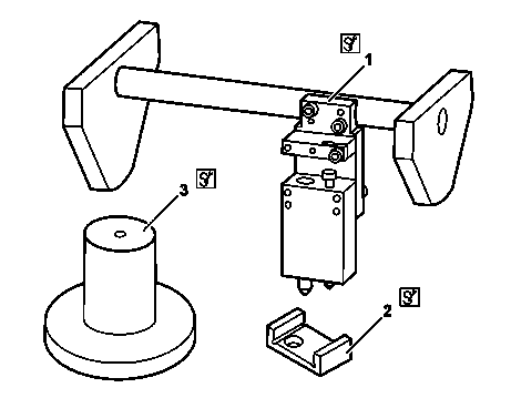
Pinion basic depth check device |
B35.30-0161-11
The caliper (2) and the standard base (3) are items that integrate the measuring device (1). The use of this device determines the standard measurement, thus, calculations are not necessary.

Differential housing measurement schematic representation) |
B35.30-0162-11
Carry out the housing measuring with the device
The procedure shown below is to determine toe standard measurement between the ring gear center and the pinion bearing housing base.
1 | Position the differential assembly housing (5), already disassembled, with the bearing seating facing upwards. |
2 | Insert the height standard block (3) of the measuring device (1) in the pinion bearing seating. |
3 | Install in the measurement device (1) the dial gauge (4), however, do not fasten it. |
4 | Use the setting tool (2) to adjust the standard measure of the measuring device (1). |
5 | Apply a pre-load of 2 mm, zero the dial indicator pointer (4) and attach it. |
6 | Install the measuring device (1) in the differential housing bearing seatings (5) so that its centering end is supported in the central hole of the height standard block (3) and, consequently, the contact point is supported at its flat surface. |
7 | Check in the dial indicator (4) if the pointer is indicating "zero" or if a shim is required. |
Normally shims are necessary between the lodging base and the pinion's bearing. The shims are supplied with thickness varying from 0.1 to 0.5 mm. Thus, determine the amount of shims that are needed to get the standard measurement, that is, to set the pointer of the dial gage (4) to "zero". |