


001 589 53 21 00
Dial gage
740 589 00 07 00
Claw-type wrench
363 589 02 21 00
Dial indicator holder

1 | After installing the wheel hub (4) on the shaft, tighten the inner slotted nut (1) using the claw wrench . |
At the same time, turn the wheel hub (4) to both sides |
2 | Apply some firm blows with a rubber hammer in the wheel hub front face |
This procedure has the purpose to assure the seating of the bearings. |
3 | Tighten the inner slotted nut (1) to the specified tightening torque . |
Turn the wheel hub again in both directions. |
4 | Loosen the inner slotted nut (1) in the specified angle at the second stage, assuring that there is an end play. . |
B35.20-0038-11
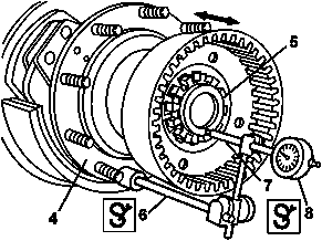
5 | Install the dial indicator holder (6) on the wheel hub (4). |
6 | Place the dial indicator (8) |
The extension (7) should lean against the axle face (5) |
7 | Set the dial indicator (8) to zero “0” with a little pre-load. |
8 | Check the wheel hub end play (4) shown in the dial indicator (8) . |
Assembly: New bearings should be adjusted with the minimum play. |
If the end play is out of the specified value | |
| |
Adjust by tightening or loosening the inner slotted nut (1). |
9 | Install a new lock plate (2) |
10 | Tighten the outer slotted nut (3) to the specified tightening torque . |
11 | Check the wheel hub end play shown in the dial indicator (8) |
If the end play is out of the specified value | |
| |
Adjust by tightening or loosening the outer slotted nut (3). |
12 | Remove the dial indicator holder (6) with the dial indicator (8). |
13 | Lock the inner slotted nut (1) by folding the lock plate (2) over the slots of the outer slotted nut (3). |
B35.20-0045-01