
711 589 01 15 00
Mandrel


D26.50-0034-01
D26.50-0033-01
1 Hold the gearbox mains shaft in a tensioning device or in a bench vise with protection jaws so that the shaft toothed end (power output side) is positioned upward.
2 Install the needle bearing (32).
3 Install the reverse gear (33).

D26.50-1151-01
4 In the cases when the assembly is disassembled, put the sliding pads (36) and the pressure springs (38) in the synchronizing body (39) and fit by the sliding sleeve (35) upper part. Lift the sliding pads (36) in the rear part with a screwdriver so that the balls (37) can be installed by the front.
Assembly position: The internal shoulder that overlaps the sliding sleeve (arrow A) and the highest collar of the synchronizing body (arrow B) must be positioned upward.

D26.50-0035-01
5 Introduce the assembly made buy the parts (35) to (39) assembled and in the correct position on the main shaft.
Assembly position: The internal shoulder that overlaps the sliding sleeve (indicated by the arrow) must be positioned upward and in the direction of the 5th speed gear.


D26.50-0030-01
D26.50-0074-01
6 Install the snap-ring (40).
Replace the snap-ring. Do not excessively open the snap-ring when performing the installation in order to not damage it.
7 Fit Assemble the synchronizing ring (46) and the synchronizing cone (41).


D26.50-0028-01
D26.50-0036-01
8 Fit the needle bearing (42) and the 5th speed gear (43).
9 Install the thrust washer (44).
Assembly position: The thrust washer plain part must be positioned downward.


D26.50-0027-01
D26.50-0026-01
10 Install the snap-ring (45).
Replace the snap-ring. Do not excessively open the snap-ring when performing the installation in order to not damage it.
11 Invert the gearbox main shaft position and attach it in a vise with protected jaws.
12 Fit the needle bearing (30).


D26.50-0025-01
D26.50-0075-01
13 Install the 1st speed gear (29).
14 Install the internal synchronizing cone (28), the synchronizing ring (27) and the external synchronizing cone (26).
Lubricate the synchronizing cones and the synchronizing ring with oil.

D26.50-0102-01
15 In the cases when the assembly is disassembled, put the sliding pads (24), the pressure springs (23) in the synchronizing body (23) in the synchronizing body of the 1st and 2nd speed gears (25) and fit by the sliding sleeve (21) upper part in the correct position. Lift the sliding pads (24) in the rear part with a screwdriver so that the balls (22) can be installed by the front.
Assembly position: The asymmetric of the sliding sleeve shoulder (arrow) and the longest collar of the synchronizing body (arrow) must be positioned upward.


D26.50-0038-01
D26.50-0021-01
16 Introduce the synchronizing body with the sliding sleeve (21) in the correct position.
Assembly position: The asymmetric of the shoulder (arrow) of the sliding sleeve (21) must be positioned upward. Pay attention to the matching position for the sliding pads with the 3 grooves of the upper synchronizing cone.
17 Assemble the snap-ring (17).
Replace the snap-ring. Do not excessively open the snap-ring when performing the installation, otherwise, the gears will not fit.

D26.50-0020-01
D26.50-0019-01
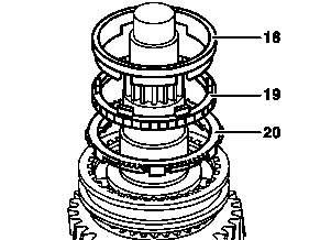
18 Fit the internal synchronizing cone (18), the synchronizing ring (19) and the external synchronizing cone (20) of the 2nd speed gear.
Lubricate the synchronizing cones and the synchronizing ring.
19 Install the needle bearing (16) and the 2nd speed gear (15).


D26.50-0018-01
D26.50-0017-01
20 Introduce the thrust washer of the 2nd speed (14) and fit it later using a mandrel (715 589 01 15 00).
21 Assemble the snap-ring (13).
Replace the snap-ring. Do not excessively open the snap-ring when assembling.


D26.50-0016-01
D26.50-0079-01
22 Install the needle bearing (12) and the 3rd speed gear (11).
23 Install the synchronizing cone (47).

D26.50-0015-01
24 Install the synchronizing ring (10).
Lubricate the synchronizing ring and the synchronizing cone with oil

D26.50-1150-01
25 In the cases when the assembly is disassembled, put the sliding pads (6) and the pressure springs (8) in the synchronizing body (9) and fit by the sliding sleeve (5) upper part in the correct position. Lift the sliding pads (6) in the rear part with a screwdriver so that the balls (7) can be installed by the front.
Assembly position: The internal shoulder that overlaps the sliding sleeve (arrow A) and the narrower collar of the synchronizing body (arrow B) must be positioned upward.


D26.50-0013-01
D26.50-0012-01
26 Fit the synchronizing body together with the sliding sleeve (5) in the correct position.
Assembly position: The internal shoulder that overlaps the sliding sleeve must be positioned upward.
27 Install the snap-ring (4).
Replace the snap-ring. Do not excessively open the snap-ring when assembling.

D26.50-0011-01
28 Assemble the synchronizing ring (3) and the synchronizing cone of the 4th speed (2).
Lubricate the synchronizing ring and the synchronizing cone with oil.
29 Introduce the main shaft in the gearbox.