
G26.31-3124-09
1 | Planetary gear set with shift mechanism | 9 | Bearing pin | 17 | Radial shaft sealing ring | ||
2 | Sliding blocks | 10 | Pulse wheel | 18 | Pilot bushing | ||
3 | Shift fork | 11 | Radial shaft sealing ring | 19 | Drift | ||
4 | Shift rod with shift piston | 12 | Output flange | B18 | Travel and speed rpm sensor | ||
5 | Range group cylinder | 13 | O-ring | A | Bores (in carrier ring) | ||
6 | Retaining ring | 14 | Pressure plate | B | Bores (in transmission housing rear part) | ||
7 | Ball bearing | 15 | Stretch bolt | C | Inscription | ||
8 | Housing (range group) | 16 | Carrier ring |

8 | Housing (range group) |
20 | Puller |
21 | Flat iron |
W26.31-1036-06

8 | Housing (range group) |
22 | Pulling device |
23 | Sleeve (pulling device) |
W26.31-1037-06
| Disassemble | ||
1 | Remove range group. | ||
2 | Remove travel and speed rpm sensor (B18). | ||
3 | Remove output flange (12). | ||
4 | Remove radial shaft sealing ring (11). | ||
5 | Remove range group cylinder (5). | ||
6 | Remove bearing pins (9). | ||
7 | Turn shift rod with shift piston (4) through 180° and pull out. | ||
8 | Detach housing (8) from planetary gear set with shift mechanism (1). | | |
Hydraulic cylinder | |||
Adapter | |||
Threaded tool | |||
Adapter | |||
Hydraulic hose (complete) | |||
Hand pump | |||
Puller | |||
9 | Remove pulse wheel (10). | ||
10 | Remove retaining ring (6). | ||
11 | Remove ball bearing (7) from housing (8). | ||
12 | Remove radial shaft sealing ring (17) and pilot bushing (18). | Counter stay | |
Internal extractor | |||
13 | Disassemble planetary gear set with shift mechanism (1). | Only if the planetary gear set with shift mechanism (1) is being repaired. | |
| Assemble | ||
14 | Assemble planetary gear set with shift mechanism (1). | Only if the planetary gear set with shift mechanism (1) has been disassembled. | |
15 | Coat new radial shaft sealing ring (17) with lubricant and install up to contact using drift (19). | Install radial shaft sealing ring (17) with the spring lock washer facing inward (oil side). | |
Synthetic grease 50 g | |||
Drift | |||
16 | Install pilot bushing (18) up to contact using drift (19). | Drift | |
17 | Install ball bearing (7) and retaining ring (6) in housing (8). | ||
18 | Install sliding blocks (2) in shift fork (3) and insert into planetary gear set with shift mechanism (1). | The inscription (arrows C) on the shift fork (3) must point towards the output. | |
19 | Align bores (A) on carrier ring (16) and bores (B) on housing (8) until they line up with each other. | ||
20 | Place housing (8) with ball bearing (7) on planetary gear set with shift mechanism (1). | ||
21 | Using pulling device (22), press housing (8) all the way onto ball bearing (7). | Hydraulic cylinder | |
Adapter | |||
Pulling device | |||
Adapter | |||
Hydraulic hose (complete) | |||
Hand pump | |||
22 | Install shift rod with shift piston (4). | The shift fork (3) must engage in the recess of the shift rod with the shift piston (4). | |
23 | Coat thread of bearing pins (9) with sealant and screw in bearing pins (9). | Shift fork bearing pin at transmission housing | |
Loctite 5203 sealant | |||
24 | Install range group cylinder (5). | ||
25 | Install pulse wheel (10) in housing (8). | ||
26 | Install new radial shaft sealing ring (11). | ||
27 | Install output flange (12). | ||
28 | Install travel and speed rpm sensor (B18). | ||
29 | Install range group. |


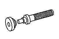
715 589 15 34 00
Hydraulic cylinder
715 589 12 34 00
Adapter
652 589 00 33 21
Hand pump
714 589 05 15 00
Drift


715 589 13 33 00
Puller
715 589 11 34 00
Adapter
000 589 33 33 00
Counter stay
715 589 12 33 00
Pulling device


715 589 11 63 00
Threaded tool
652 589 00 33 23
Hydraulic hose (complete)
000 589 27 33 00
Internal extractor