
G26.10-3256-09
1 | Compressed-air line | 14 | Reverse gear | 27 | Tapered roller bearing outer race | ||
2 | Splitter group cylinder | 15 | Center section of transmission housing | 28 | Countershaft brake | ||
3 | Splitter group shift rod | 16 | Shim | 29 | Drive shaft bearing cap | ||
4 | Front section of transmission housing | 17 | Tapered roller bearing outer race | 30 | Reverse idler shaft | ||
5 | Screw plug | 18 | Range group | 31 | Threaded insert | ||
6 | Springs | 19 | Main shaft | 32 | Slide hammer puller | ||
7 | Catch bolt | 20 | Synchronizer cone with synchronizer ring and annular spring | 33 | Retaining ring | ||
8 | Sliding blocks | 21 | Sliding sleeve | B501 | Main shaft rpm sensor | ||
9 | Oil pipe | 22 | Drive shaft | B502 | Countershaft rpm sensor | ||
10 | Shift fork for splitter group | 23 | Electric line | B505 | Transmission oil temperature sensor | ||
11 | Countershaft | 24 | Shift | A | Position of reverse idler gear | ||
12 | Tapered roller bearing outer race | 25 | Bearing pin | ||||
13 | Shift unit | 26 | Tapered roller bearing outer race |

9 | Oil pipe |
11 | Countershaft |
13 | Shift unit |
15 | Center section of transmission housing |
19 | Main shaft |
50 | Holding device |
W26.50-1170-06

4 | Front section of transmission housing |
43 | Pulling device |
44 | Adapter |
W26.10-1141-02

19 | Main shaft |
69 | Oil restrictor |
W26.50-1218-06

72 | Transmission |
73 | Assembly device |
W26.50-1216-12
Warning | Risk of injury. Moving parts can pinch, crush or, in extreme cases even sever extremities. | No parts of the body or limbs should be within the operating area of mechanical components when moving components. | |
Caution | Risk of injury to skin and eyes due to handling of transmission oil. Health risk caused by swallowing transmission oil | Wear protective gloves, protective clothing and safety glasses. | |
Topical note | Information on preventing damage to electronic components due to electrostatic discharge | ||
Notes on compressed air connection systems | |||
| Disassemble | ||
1 | Remove transmission (72). | Choose procedure according to accessibility and design. | |
2 | Disconnect electrical connectors from transmission control unit (TCM) (A5), pneumatic central clutch release bearing, transmission oil temperature sensor (B505), main shaft rpm sensor (B501) and countershaft rpm sensor (B502). | ||
3 | Detach compressed-air lines from transmission positioner (Y900), range group cylinder and power take-off. | ||
4 | Detach compressed-air lines and electrical lines (23) with brackets from transmission (72). | ||
5 | Remove pneumatic central clutch release bearing. |
| |
6 | Remove range group (18). | ||
7 | Remove oil restrictor (69) from main shaft (19). | Only if fitted. | |
8 | Remove transmission oil temperature sensor (B505). | ||
9 | Remove countershaft rpm sensor (B502). | ||
10 | Remove main shaft rpm sensor (B501). | ||
11 | Remove transmission positioner (Y900). |
| |
Transmission positioner from the company Wabco | |||
12 | Remove gearshift system (24). | ||
13 | Remove reverse idler shaft (30) using threaded insert (31) and impact extractor (32). | ||
| Threaded insert for removing reverse idler shaft | ||
Impact extractor | |||
14 | Remove splitter box cylinder (2). | ||
15 | Remove splitter box shift piston. | ||
16 | Attach assembly tool to splitter box shift rod (3). | ||
| |||
17 | Install assembly device (73) at transmission (72) and position vertically. | ||
Assembly device | |||
18 | Unscrew screw plug (5) and remove springs (6) and catch bolt (7). | The screw plug (5) is spring-loaded. | |
19 | Remove countershaft brake (28). | ||
20 | Remove drive shaft bearing cap (29). | ||
21 | Remove retaining ring (33) on oil pipe (9). | ||
22 | Unscrew both bearing pins (25). | Extraction claw | |
Impact extractor | |||
23 | Remove screws around circumference of transmission housing center section (15). | ||
24 | Attach pull-off device (43), thrust piece 03, hand pump, hydraulic hose, hydraulic cylinder and the two adapters (44) to transmission housing front section (4). | disassembly kit | |
Puller | |||
Hand pump | |||
Hydraulic hose (complete) | |||
Hydraulic cylinder | |||
Adapter | |||
Adapter | |||
25 | Press transmission housing front section (4) approx. 30 mm off transmission housing center section (15). | Do not damage sealing surfaces. | |
26 | Unhook splitter box shift rod (3) from splitter box shift fork (10) and pull out of transmission housing front section (4) using assembly tool. | ||
| Assembly tool for installing shift rod of splitter group | ||
27 | Detach hand pump, hydraulic hose, hydraulic cylinder and the two adapters (44). | ||
28 | Attach holding device to pull-off device (43). | Retaining device | |
Puller | |||
29 | Remove transmission housing front section (4). | ||
30 | Detach holding device, pull-off device (43) and thrust piece 03 from transmission housing front section (4). | ||
31 | Remove radial shaft sealing ring and pilot bushing for splitter box shift rod (3) from transmission housing front section (4). | ||
| Adapter for removing guide bush in front section of transmission housing | ||
Counter stay | |||
Internal extractor | |||
32 | Remove tapered roller bearing outer races (26, 27) from transmission housing front section (4). | Use a suitable drift. | |
33 | Remove splitter box shift fork (10) with sliding blocks (8). | ||
34 | Push countershaft (11) to one side and remove drive shaft (22). | ||
35 | Remove sliding sleeve (21). | ||
36 | Remove synchronizer cone with synchronizer ring and annular spring (20). | ||
37 | Attach holding devices (50) to main shaft (19), countershaft (11), shift unit (13) and oil pipe (9). | Retaining device | |
Holding fixture | |||
38 | Push reverse idler gear (14) to one side (arrow A), remove main shaft (19), countershaft (11), shift unit (13) and oil pipe (9) from transmission housing center section (15) and clamp in clamping device. | Clamping device | |
39 | Remove oil pipe (9). | ||
40 | Remove countershaft (11) from holding device (50). | ||
41 | Remove shift unit (13) from holding device (50) and from main shaft (19). | ||
42 | Remove main shaft (19) from holding device (50). | ||
43 | Remove reverse idler gear (14) from transmission housing center section (15). | ||
44 | Remove tapered roller bearing outer race (12) from transmission housing center section (15) using a suitable drift. | ||
45 | Remove tapered roller bearing outer race (17) and spacer disk (16) from transmission housing center section (15) using a suitable drift. | ||
46 | Detach assembly device (73) from transmission housing center section (15) and set down horizontally. | ||
47 | Disassemble main shaft (19). | ||
48 | Disassemble drive shaft (22). | ||
49 | Disassemble countershaft (11). |


715 589 19 63 00
disassembly kit
715 589 08 31 00
Assembly device
715 589 12 34 00
Adapter
652 589 00 33 21
Hand pump


715 589 11 34 00
Adapter
715 589 06 33 00
Extraction claw
715 589 06 31 00
Holding fixture
315 589 02 31 00
Clamping device


652 589 00 33 23
Hydraulic hose (complete)
715 589 01 31 00
Retaining device
715 589 15 34 00
Hydraulic cylinder
715 589 08 33 00
Puller


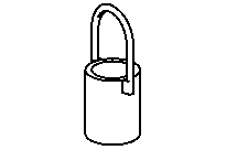

000 589 33 33 00
Counter stay
355 589 01 63 00
Impact extractor
715 589 05 31 00
Retaining device
000 589 27 33 00
Internal extractor
Odkazované dokumenty
- ah0018n000101a Pokyny k systémům konektorových spojů tlakového vzduchu
- ah5400p000101a Upozornění k zamezení poškozením elektronických součástí elektrostatickým výbojem
- ar2520g0182n
- ar2610w000101he Montáž a demontáž montážního přípravku převodovky
- ar2618g1001ad
- ar2621g0006ad
- ar2621g0006adb
- ar2630g1020ad
- ar2631g3100ad
- ar2635g0001ad
- ar2635w000201ha Demontáž, montáž radiálního kroužku těsnění hřídele a vodicího pouzdra tyče řazení skupiny půlení
- ar2635w000201ha
- ar2650g0004ad
- ar2650g0427ad
- ar2650g4744ad
- ar2650g4775ad
- ar2650g6000ad
- ar2660g0001ad
- as0000z000901a Nebezpečí poranění přivřením nebo přiskřípnutím, v extrémním případě amputací končetin při zásazích do mechaniky
- as0040z000101a Nebezpečí poranění kůže a očí při manipulaci s převodovým olejem. Nebezpečí ohrožení zdraví při požití převodového oleje
- wf5850n100001a
- wf5850n263502a
- wf5850n265006a