
General
In 10/2015 the 2nd generation of the engine OM 471 was added to the engine range. Vehicles equipped with this have an additional code M5B (2nd generation engine OM 471), apart from the actual engine code that describes the power stage.
The further-developed engine is based on the predecessor model which takes the following basic data as basis:
Type of construction: 6-cylinder inline engine
One-piece 4-valve cross-flow cylinder head
Two camshafts located at the top
Gearwheel drive at the rear on the output side of engine
Common rail with pressure boost
Engine brake as per the Jake brake principle
Cooled exhaust gas recirculationDiscontinuation of boost pressure control, EGR sensor and EGR control
On the latest generation of the OM 471, the boost pressure control is also discontinued apart from the boost pressure control valve (wastegate) for the turbocharger. In combination with the discontinuation of the EGR sensor and the EGR control, this means: the thermodynamically optimized engine runs in a pre-controlled manner. Through pre-controlling of all parameters, optimum efficiency is achieved without having to go through individual controls and their combinations. Even the emission control overlays the hitherto usual individual control of exhaust gas recirculation and boost pressure and, in this way, works more effectively.
Due to these and other changes as compared to the predecessor variant, it has been possible to improve the engine considerably with regard to the following values:
Higher torque even at the lowest rpms
Better vehicle dynamics in connection with tall axle ratios
Reduced consumption of diesel fuel of up to 3 % with only slightly increased quantities of AdBlue® (approx. 5 %)
Increased robustness due to discontinuation of sensors and pre-controlled operationOverview of new features
Improved diesel fuel injection system
Improved compression ratio
Modified cylinder head
Optimized coolant circuit
Optimally tailored turbocharger developed in-house
Lesser friction losses
Optimized gearwheel drive
New oil circuit
Improved Euro VI management
AdBlue® consumption amounts to approx. 5 % of the diesel consumption as against previous consumption of 3 %
Additional fifth power stage with 390 kW (530 PS)
Changed exhaust gas recirculation
W01.00-1160-76
Available power stages
In addition to the four power stages from 310 to 375 kW so far, the engine OM 471 has been available in the variant with 390 kW and correspondingly higher torque since 04/2016. This engine has the code M3E (engine OM471, R6, 12.8 l, 390 kW (530 PS), 2600 Nm).
Top Torque special equipment
As in case of the 1st generation of OM 471, the three basic power variants with 310, 330 and 350 kW are available with the special equipment "Top Torque". This is indicated by the additional code M0E (Torque increase, in 12th gear). Vehicles with this code possess a different data record, whereby a torque increase of approx. 200 Nm takes place when driving in 12th gear at 1100 rpm.
Power and torque curves with new characteristics in comparison with the 1st generation
In comparison with 1st generation, the maximum values of power and torque are unchanged. However, the power and torque curves rise considerably in the lower rpm range. In all available engine power stages, a torque of at least 2000 Nm is already applied at a speed of under 800 rpm. Similarly, at a rated speed of 1600 rpm reduced from 1800 rpm, 95 % of the maximum power is already achieved at approx. 1300 to 1400 rpm. For details see: Technical data of engine OM 471.
New products/features in detail
Details of the changed engine components on OM 471 of the 2nd generation are as follows.

Cylinder head
The construction of the cylinder head (1) has been changed in such a way that the outlet side (3) is now more rigid. Furthermore, the oil return lines have been changed.
1 | Cylinder head |
2 | Outlet duct |
3 | Exhaust side |
x | Direction of travel |
W01.30-1252-75

Cylinder head cover
The new engine now has a uniform cylinder head cover (1) for all power stages. Besides the reduction in the variety of variants, there has also been a reduction in noise emissions.
1 | Cylinder head cover |
W01.20-1084-76

Crankcase, cylinder liners, cylinder head gasket
Changes have been made to the crankcase (1) such as modified or discontinued mounting points or the flange for the turbocompound system that was closed with a cap so far and which was only available for engine OM 473.9 until now. This opening of the flange is now closed. Moreover, the geometry of the oil return lines has been optimized.
The cylinder liners (2) now have optimized honing in order to reduce friction losses. At the cylinder head gasket (3), the sealing track of the oil return line elastomers has been adapted to the modified crankcase (1) and the modified cylinder head.
1 | Crankcase |
2 | Cylinder liners |
3 | Cylinder head gasket |
W01.40-1214-76

Pistons, piston rings
The compression ratio has been increased from 17.3:1 to 18.3:1 through the use of new pistons (1). This corresponds to an increase of almost 7 %.
The combustion system has been influenced by the changed geometry of the piston combustion cavity (2). It is now a stepped cavity.
The bevel-edged ring has been changed for reducing friction losses. It has been changed in such a way that it now has reduced tangential force.
1 | Piston |
2 | Piston combustion cavity |
W03.10-1205-81

Connecting rod
The material for the connecting rod (2) has been changed from 36MnVS4mod to 46MnVS6mod.
1 | Crankshaft |
2 | Connecting rod |
3 | Connecting rod bearing |
W03.10-1207-81

Crankshaft
The new engine has a crankshaft which weighs lesser. In addition, its flash seams have been moved.
1 | Crankshaft |
2 | Main bearing |
3 | Fitted bearing |
W03.20-1315-81

Vibration damper
The vibration damper (1) has been adapted to the changed compression ratio or combustion. The weight has been reduced by 15 % to 3.1 kg.
1 | Vibration damper |
W03.30-1158-81

Camshaft case
The oil circuit in the camshaft housing (1) has been optimized.
1 | Camshaft case |
W05.20-1067-76

Diesel injection system
The new engine has the common rail diesel injection system X-Pulse of the 2nd generation. The following components have been changed compared to the 1st generation: injectors (4), rail (5), high-pressure lines (3, 6), fuel system high pressure pump (1), and charge air distributor and camshaft case that have been adapted accordingly. The maximum fuel pressure in rail (5) has been increased from 900 to 1160 bar. The injection pressure now reaches up to 2700 bar as compared to the previous 2300 bar.
Another new feature is the so-called asymmetric injection. This means that all cylinders are supplied with the same quantity of fuel while driving normally. It works differently in case of regeneration of the diesel particulate filter under low load: in this case, the fuel quantity in the cylinders 1 to 3 is continuously reduced while the exhaust gas recirculation rate simultaneously increases. At the same time, the fuel quantity in the cylinders 4 to 6 is increased. If necessary, the injection quantity in the cylinders 1 to 3 can be reduced to zero, and at the same time, it can be increased to the maximum level for cylinders 4 to 6.
1 | Fuel system high pressure pump |
2 | Fuel filter module |
3 | High-pressure lines |
4 | Injectors |
5 | Rail |
6 | High-pressure lines |
7 | Return lines |
8 | Fuel line (feed line from filter) |
9 | Fuel line (return flow to fuel tank) |
10 | Fuel line (return line to filter) |
11 | Fuel line (feed line to fuel tank) |
B622 | Rail pressure sensor |
W07.00-1013-76

Injector
The injectors (1) now have eight holes instead of seven, as was the case so far. The maximum fuel flow rate thus increases by around 10 % and now amounts to 570 to 870 cm3/30 s.
The gear ratio in the pressure transducer is 2.2.
1 | Injector |
W07.00-1014-81

Fuel filter module
The feed lines and return lines to the fuel system high pressure pump at the fuel filter module (1) have been changed.
1 | Fuel filter module |
W47.20-1158-76

Turbocharger
The OM 471 of the 2nd generation has a completely newly developed turbocharger (1). It is a Mercedes-Benz in-house development and it is also produced in-house.
Due to direct adaptation to the engine, a quick and high power increase is achieved even at low rotational speeds. Like in case of the predecessor, its construction is an asymmetric turbocharger (1) with correspondingly asymmetric air supply.
The turbocharger (1) has a fixed turbine geometry and thus works without additional moving parts, in contrast to turbochargers with variable turbine geometry. This variant is technically much less complicated and thus also much less susceptible to damage. Discontinuation of boost pressure control valve (wastegate) also contributes to its technical simplification. It reduces the complexity of the turbocharger (1) further and eliminates potential sources of fault such as leaks.
The turbine wheel housing is made of cast iron with spheroidal graphite EN1563 GJS-X (SiMo 5-1). The impeller wheel is made of aluminum alloy EN1706-AC-42100 (AlSi7Mg0.3). As in case of the predecessor, the forces that act on the shaft of the impeller wheel or the turbine are absorbed by plain bearings.
1 | Turbocharger |
2 | Exhaust manifold center section (with exhaust gas recirculation flap of exhaust gas recirculation) |
A | Intake air (from air filter) |
B | Charge air (to charge air cooler) |
C | Exhaust |
W09.40-1310-76

Oil/coolant module
The coolant pump (2) integrated in the oil/coolant module (1) now has a belt pulley that has been reduced in diameter.
1 | Oil/coolant module |
2 | Coolant pump |
W18.20-1055-76
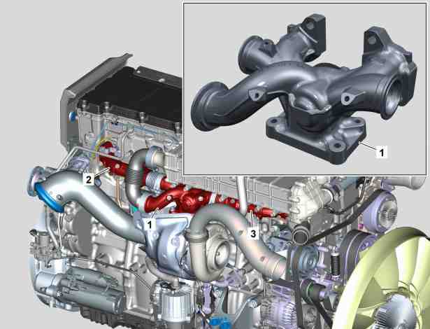
Exhaust manifold
The exhaust manifold center section (1) has been changed with regard to the modified exhaust gas recirculation in such a way that the exhaust gas recirculation flap is now integrated in it.
For details see: Section on exhaust gas recirculation.
1 | Exhaust manifold (center section) |
2 | Exhaust manifold (rear section) |
3 | Exhaust manifold (front section) |
W14.10-1083-76

Exhaust gas recirculation
The position of the exhaust gas recirculation flap (6) has been moved far forward. It is now in the exhaust manifold center section (2). In order to achieve high boost pressure quickly and a correspondingly quick increase in output and torque, the exhaust gases of cylinders 4 to 6 (B) are guided directly to the turbine of the turbocharger (3) without any loop way. From the exhaust gases of cylinders 1 to 3 (A), a certain predefined exhaust gas quantity is branched off for the exhaust gas recirculation. This helps in reducing NOx emissions in particular.
If the distribution of exhaust gases between the exhaust manifold and turbocharger (3) was determined by, among other things, the construction of the exhaust manifold and the geometry of the asymmetric turbocharger (3) so far, then the distribution is now continuous and can be regulated very accurately in the entire range of the engine characteristic map. This results in effective thermal management and a generally low exhaust gas recirculation rate with advantages of fuel economy. Thanks to the new position of the exhaust gas recirculation flap (6), the exhaust gas recirculation rate as well as the exhaust flow to the turbocharger (3) can be controlled according to the operating characteristics of the engine. Recording of the exhaust gas recirculation in the exhaust gas recirculation line (4) upstream of exhaust gas recirculation cooler (1) by the exhaust gas recirculation (EGR) differential pressure sensor and downstream control of the exhaust gas recirculation is thus not required any more.
The exhaust gas recirculation flap (6), in its new position, that can be steplessly controlled via the exhaust gas recirculation controller also results in a new scope of asymmetry: between 0 and 100 % of the exhaust gases from the three supplying cylinders can be supplied to the combustion process depending on the requirement. The exhaust gas recirculation positioner thus not only controls the exhaust flow to the exhaust gas recirculation, but also to the turbocharger (3).
1 | Exhaust gas recirculation cooler |
2 | Exhaust manifold center part |
3 | Turbocharger |
4 | Exhaust gas recirculation line |
5 | Exhaust pipe |
6 | Exhaust gas recirculation flap |
A | Exhaust gases (from cylinder 1 to 3) |
B | Exhaust gases (from cylinder 4 to 6) |
C | Exhaust gases (branched off to exhaust gas recirculation) |
D | Exhaust gases (branched off to impeller wheel of turbocharger (3)) |
W14.20-1113-76

Exhaust gas recirculation flap (6) partially open
With this position of the exhaust gas recirculation flap (6), a predefined portion of the exhaust gases from cylinders 1 to 3 (A) is led towards the exhaust gas recirculation and into the turbine of the turbocharger.
2 | Exhaust manifold center part |
6 | Exhaust gas recirculation flap |
A | Exhaust gases (from cylinder 1 to 3) |
B | Exhaust gases (from cylinder 4 to 6) |
C | Exhaust gases (branched off to exhaust gas recirculation) |
D | Exhaust gases (branched off to impeller wheel of turbocharger) |
W14.20-1114-75

Exhaust gas recirculation flap (6) completely closed
With this position of the exhaust gas recirculation flap (6), the exhaust gases from cylinders 1 to 3 (A) are led completely in the direction of the impeller wheel of the turbocharger. The exhaust gas recirculation rate is equal to zero.
2 | Exhaust manifold center part |
6 | Exhaust gas recirculation flap |
A | Exhaust gases (from cylinder 1 to 3) |
B | Exhaust gases (from cylinder 4 to 6) |
D | Exhaust gases (branched off to impeller wheel of turbocharger) |
W14.20-1115-75

Exhaust gas recirculation flap (6) completely open
With this position of the exhaust gas recirculation flap (6), all the exhaust gases from cylinders 1 to 3 (A) are led towards the exhaust gas recirculation. This corresponds to the maximum possible exhaust gas recirculation rate.
2 | Exhaust manifold center part |
6 | Exhaust gas recirculation flap |
A | Exhaust gases (from cylinder 1 to 3) |
B | Exhaust gases (from cylinder 4 to 6) |
C | Exhaust gases (branched off to exhaust gas recirculation) |
W14.20-1116-75

Exhaust gas recirculation line (1) (downstream of exhaust gas recirculation cooler)
The exhaust gas recirculation line (1) has been changed. The exhaust gas recirculation (EGR) differential pressure sensor installed so far has been discontinued (see exhaust gas recirculation).
1 | Exhaust gas recirculation line (downstream of exhaust gas recirculation cooler) |
W14.20-1118-76

Engine brake
The engine brake system has been changed in comparison to the 1st generation OM 471. Among other points, this is associated with the discontinuation of the boost pressure control valve (wastegate) at the turbocharger. Like in the 1st generation, the exhaust gas recirculation controller or the exhaust gas recirculation flap is also used for regulating the engine brake power. There are still three different brake stages which are activated via the engine brake switch.
Brake stage I: brake power is achieved by cylinders 1 to 3. The exhaust gas recirculation flap is completely open.
Brake stage II: brake power is achieved by cylinders 1 to 3. The exhaust gas recirculation flap is completely closed.
Brake stage III: brake power is achieved by cylinders 1 to 6. The exhaust gas recirculation flap is partially open.
1 | Exhaust rocker arm combination (cylinder 1) |
2 | Exhaust rocker arm combination (cylinder 2) |
3 | Exhaust rocker arm combination (cylinder 3) |
4 | Exhaust rocker arm combination (cylinder 4) |
5 | Exhaust rocker arm combination (cylinder 5) |
6 | Exhaust rocker arm combination (cylinder 6) |
7 | Exhaust gas recirculation flap |
8 | Exhaust manifold center part |
I | Position of exhaust gas recirculation flap (with brake stage I) |
II | Position of exhaust gas recirculation flap (with brake stage II) |
III | Position of exhaust gas recirculation flap (with brake stage III) |
W14.15-1159-76

Oil pump
For oil pump (1), the gear pairs have been revised.
1 | Oil pump |
2 | Drive gear |
W18.10-1063-81

Engine power take-off
The engine power take-off (1) has been optimized.
1 | Engine power take-off |
W23.20-1097-76