SI07.03-B-0003A | Service Information: Bleeding of fuel line with electric pump | 12.02.16 |
Cumbustion engine 372, 374, 376, 377 with Vehicle 364, 382, 384, 386, 682, 688, 693, 694, 695
Cumbustion engine 457 with Vehicle 382.### #C, 382.### #A, 382.### #D, 382.### #H, 634.0## #C, 634.0## #A, 634.0## #D, 634.0## #H, 664.### #C, 664.### #A, 664.### #D, 664.### #H, 693.### #C, 693.### #A, 693.### #D, 693.### #H, 695.### #C, 695.### #A, 695.### #D, 695.### #H, 696.### #C, 696.### #A, 696.### #D, 696.### #H
Cumbustion engine 460 with Vehicle 634.### #M, 634.### #D
Cumbustion engine 475, 476 with Vehicle 382.### #C, 382.### #A, 382.### #B, 382.### #D, 386.### #C, 386.### #A, 386.### #B, 386.### #D, 388.### #C, 388.### #A, 388.### #B, 388.### #D, 398.### #C, 398.### #A, 398.### #B, 398.### #D, 660.### #C, 660.### #A, 660.### #B, 660.### #D, 664.### #C, 664.### #A, 664.### #B, 664.### #D, 695.### #C, 695.### #A, 695.### #B, 695.### #D
Cumbustion engine 541 with Vehicle 934.### #R, 934.### #S
Cumbustion engine 904, 906, 924, 926 with Vehicle 368, 382, 384, 634.0, 688, 693, 694, 695, 958, 979
We hereby inform that a case containing the fuel system draining equipment supplied by the firm of Especifer, approved by us as a supplier of conventional accessories and tools, is now available for purchase.Use of this equipment renders injection tube removal unnecessary for draining the fuel system.
Re-use of injection tubes is not allowed, according to SI07.15-B-0008A.
Note:This information does not imply any association or commitment between Mercedes-Benz do Brasil S.A. and the aforementioned supplier/manufacturer, or responsibility as to the quality of goods supplied.
Approved supplier of conventional accessories and tools.
Especifer Indústria e Comércio de Equipamentos Ltda
Avenida Horst Frederico João Herr, 1945 - Europark Comercial - Indaiatuba - São Paulo
Phone: +55 (19) 3936-9797


B07.03-0012-01
B07.03-0013-01
Fuel system draining equipment with its components
A - Case containing fuel system draining equipment
2A/2B - Hoses (2 pieces)
8 - Electric wiring harness
13 - Sealing rings (4 pieces)
14 - Adapter tubes (2 pieces)
17 - Banjo type ring pieces (2 pieces)
18 - Hollow screws (2 pieces)
Technical data
Power supply: 12 V
Pressure: 4 bar
Rotation: 2.800 r.p.m
Flow: 10 l / min
Working temperature: -20 ºC to 40 ºC
Maximum operating cycle: 30 minutes
Current: 40 A
To be used for Diesel fuel only.

B07.03-0008-06
A - For vehicles with fuel lines equipped with rapid connection fittings
1 - Engine fuel supply line - detached from tank
2A - Suction hose of the draining equipment case connected to the fuel tank
2B - High pressure output hose of the fuel system draining equipment case
3 - Input connector - suction side
4 - Output connector - pressure side
5 - Fuel input line
6 - Fuel input from Racor filter
7 - Racor filter
8 - Wiring harness with battery terminal clips
9 - Connector/ Fuse
10 - Starter button
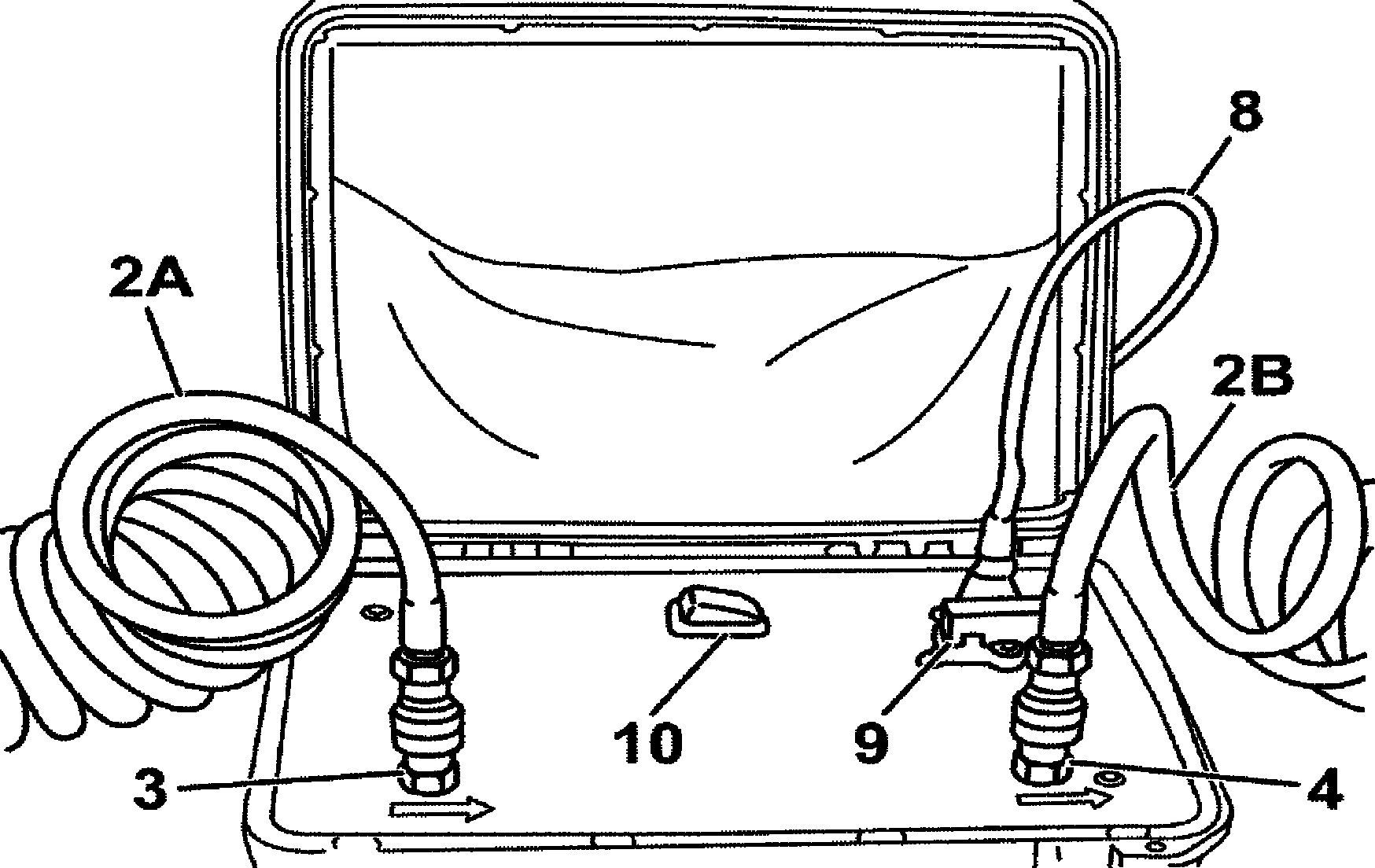

B07.03-0009-01
B07.03-0011-01
B - For vehicles with fuel lines equipped with banjo type ring piece fittings
2A/2B- Hoses
3 - Input connector
4 - Output connector
8 - Wiring harness with battery terminal clips
9 - Electric connector
10 - Starter button
13 - Sealing rings
14 - Connection tube
15 - Fuel supply line - suction side
16 - Fuel output line to engine - pressure side
17 - Banjo type ring piece fittings
18 - Hollow screw

B07.03-0010-01
11 - Fuel return line
Operating procedures for the fuel system draining equipment case
For the following procedures the fuel tank must be at least 1/4 full.
Do not start the fuel system draining equipment before all fuel lines and hoses are correctly installed.
To be used for Diesel fuel only
Danger! | Risk of explosion due to the fuel ignition. Risk of injury on the skin and eyes due to the leaks of fuel jets | Withdraw all inflammable materials from the danger zone. No work on pressurized systems to be executed. | |
Danger! | Danger of explosion of inflammable material, risk of poisoning through inhalation and ingestion of fuel and risk of injury by eye and skin contact with fuel | Forbidden to build fire, produce sparks, naked flames and strictly no smoking.Fuel to be stored only in appropriate vessels with adequate identification. When handling fuel, always wear appropriate protective equipment and clothing. | |
| The fuel system draining equipment case offers optional adaptation for rapid connection fittings (A) or for banjo type ring piece fittings (B) | Use banjo type ring piece fittings or rapid connection fittings as needed. | |
| A - For vehicles with fuel lines equipped with rapid connection fittings | ||
1a | Separate the fuel line (1) with rapid connection fittings from the fuel tank | ||
2a | Connect hose (2A) to the fuel tank outlet and to the input connector (3) of the draining equipment case | ||
3a | Remove the Racor filter input line (5) (tube with white collar) | ||
4a | Connect hose (2A) to the fuel input of Racor filter (6) and to output connector (4) of the draining equipment case | ||
5a | Connect wiring harness (8) to connector (9) of the equipment case | Connect the terminal clips (black and red) to the battery poles. Working tension is 12 Volts. | |
6a | Press button (10) to the Start position | ||
7a | Fuel should leave normally through return line (11) | Minimum operating time for the fuel system draining equipment case is five minutes. | |
| B - For vehicles with fuel lines equipped with banjo type ring piece fittings | Attach banjo type ring piece fittings (17) to hoses (2A and 2B). | |
1b | Remove input line (16) from the Racor filter (white ring) | ||
2b | Attach line (16) to connection tube (14) together with hose (2A) | Fit sealing rings (13) between the ring pieces (hose and line) fastening the ring pieces with hollow screw (18). | |
3b | Remove line (15) from the Racor filter output | ||
4b | Connect output line (15) to connection tube (14) together with pump high pressure hose (2B) | Fit sealing rings (13) between the ring pieces (hose and line) fastening the ring pieces with hollow screw (18). | |
5b | Connect wiring harness (8) to connector (9) of the equipment case | Connect the terminal clips (black and red) to the battery poles. Working tension is 12 Volts. | |
6b | Press button (10) to the Start position | ||
7b | Fuel should leave normally through return line (11) | Minimum operating time for the fuel system draining equipment case is five minutes. |