33 - 3500.02 Removal, disassembly, assembly and installation of steering knuckle (with needle bearings)
Preliminary work:
Remove front wheel hub (33-2200)
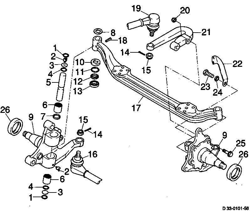
1 Snap ring check, replace, if required
2 Grease nipple
3 Cap replace
4 Sealing ring replace
5 Kingpins check, replace, if required
6 Needle bearing replace, grease
7 Shaft seal replace, grease sealing lip
8 Shim measure, install correct thickness
9 Steering knuckle check, replace, if required
10 Retaining ring (steering side) replace
11 Shaft seal (steering side) replace, grease sealing lip
12 Thrust washer (steering side) replace
13 Axial roller bearing (opposite steering side) replace, grease
14 Cotter pin replace
15 Crown nut M 14x1.5 90...100 Nm
16 Tie rod
17 Axle beam
18 Clamping sleeve replace
19 Drag link
20 Nut replace M 12x1.5 110...125 Nm
M 14x1.5 170...195 Nm
21 Steering arm
22 Retainer
23 Bolt for steering end stop
24 Nut M 10 40...45 Nm
25 Bolt
26 Thrust ring check, replace if required
Adjustment values |
Front steering knuckle on axle beam mm 0.01 - 0.1 |
Wheel lock angle max. Degrees 52 |
Capacity |
Multiple-purpose grease per steering knuckle according to sheet no. 267* g 15 |
* MB Specifications for Service Products


Special tools
auspressen
bolzen 23
Führungs-
dorn 23
dorn aus-
ein nadel
23
dorn auspr
bolzen
23+26
hydr. press
komplett


abzieher
spurstange
einpressen
nadel+
rwd 23
achsfaust
wärmer
23
achsfaust
wärmer
26
zentrier
dorn 26

einpressen
nadel+
rwd 26
dorn aus
ein nadel
26
Removal, disassembly
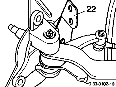
1 Screw retainer (22) off of steering knuckle and remove.
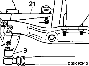
2 Remove cotter pins from crown nuts on steering arm (21) on steering side as well as on knuckle arms (9) on left and right and screw off nuts.
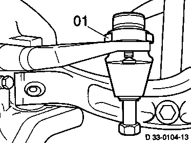
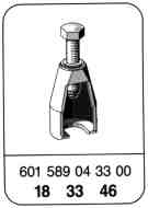
3 Pull drag link off of steering arm with special tool (01).
Note
Do not damage rubber cap.
(01) 601 589 04 33 00

4 Press tie rod on left and right out of knuckle arm with special tool (01).
Note
Do not damage rubber cap.
(01) 601 589 04 33 00
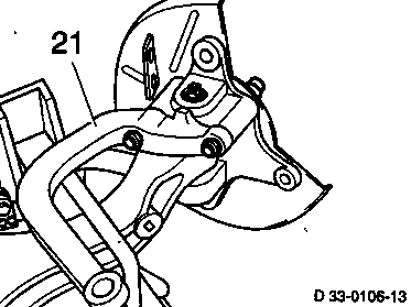
5 Screw steering arm (21) off of steering knuckle.
6 On vehicles with ABS:
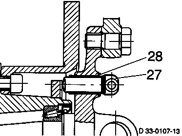
Pull ABS sensor (27) out of steering knuckle and tie up in wheelhouse.
Note
Replace clamping sleeve (28) each time rod sensor (27) is removed and install with acid-free grease (silicone grease Molykote 44 Light).
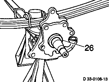
7 Before removing steering knuckle check the running surface on the thrust ring (26) provided with a swirl for the wheel hub sealing ring for wear. If removal is necessary, drill thrust ring and break open.
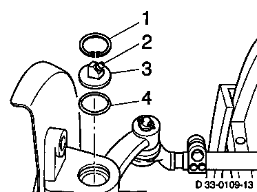
8 Remove snap rings (1) at top and bottom of steering knuckle, remove caps (3) with sealing rings (4).

9 Drive clamping sleeve (arrow) out of front axle beam with drift punch.

10 Press kingpins out of front axle beam with hydraulic press (02), sleeve (03) and punch (04).
11 Remove steering knuckle, axial roller bearing and shim.
(02) 000 589 92 33 00
(04) 601 589 03 15 00
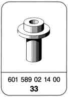
(03) Dia. 23 mm 601 589 02 14 00
(03) Dia. 26 mm 000 589 92 33 17

12 Drive needle bearing and shaft seal out of steering knuckle with special tool (05).
13 Clean all parts, check for wear and replace if required.
(05) Dia. 23 mm 601 589 02 15 00
(05) Dia. 26 mm 730 589 02 15 00

Assembly and installation
1 Check steering knuckle before installation.
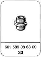
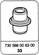
2 Drive needle bearing into steering knuckle with special tool (05). Drive in needle bearing with special tool (06) in order to ensure maintenance of the specified clearance for the bearing and upper sealing ring.
(05) Dia. 23 mm 601 589 02 15 00
(06) Dia. 23 mm 601 589 08 63 00
(05) Dia. 26 mm 730 589 02 15 00
(06) Dia. 26 mm 730 589 00 63 00
Note
Install sealing ring in upper needle bearing so that sealing lip points downward.

3 Position steering knuckle on front axle beam together with axial roller bearing and shim and center with special tool (07).
(07) Dia. 23 mm 601 589 01 15 00
(07) Dia. 26 mm 309 589 00 15 00

4 Install steering knuckle without end play if possible. The end play can be compensated by installing shims (8) available in various thicknesses. The end play must be measured separately on each steering knuckle under all circumstances.
8 Shim
10 Retaining ring
11 Shaft seal
12 Thrust washer
17 Stub axle
Note
During assembly ensure that the collar on the thrust washer (12) is flush on the steering knuckle.
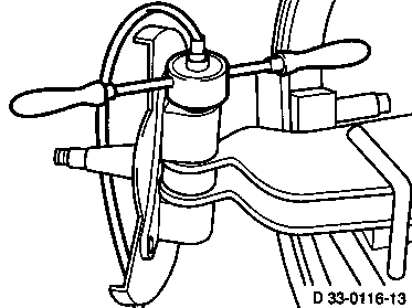
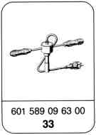
5 Heat stub axle up to approx. 200...220 °C (yellow temper color) with special tool .
Note
The kingpin should be cooled to the extent possible to facilitate assembly.
Dia. 23 mm 601 589 09 63 00
Dia. 26 mm 309 589 03 63 00

6 Guide steering knuckle from below with special tool (07) and insert kingpin so that clamping sleeve can be installed.
(07) Dia. 23 mm 601 589 01 15 00
(07) Dia. 26 mm 309 589 00 15 00
7 Drive clamping sleeve into front axle beam.
8 Install sealing rings (4), caps (3) and snap rings (1). Screw in grease nipple (2).
9 Grease steering knuckle with specified quantity of grease.
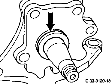
10 Heat thrust ring up to approx. 80 °C. Use suitable pipe to install and ensure that thrust ring is pressed against the machined surface of the steering knuckle (arrow). Check whether thrust ring is flat against contact surface.
Note
Observe color code on thrust rings.
Yellow: Left with right-hand twist
Red: Right with left-hand twist
11 On vehicles with ABS:
Install ABS sensor (27) and slide into installation hole against stop.
Note
Replace clamping sleeve (28) each time rod sensor (27) is removed and install with acid-free grease (silicone grease Molykote 44 Light).
12 Screw steering arm (21) onto steering knuckle and tighten to 110...125 Nm.
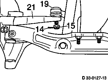
13 Insert drag link (19) into steering arm (21) and tighten crown nut (15) to 90...100 Nm.
14 Insert cotter pin into crown nut.
Note
Do not loosen crown nut to insert cotter pin.
Ensure that ball heads are centered (ball pins to ball sockets). If not, loosen clamp and correct position of ball heads.

15 Insert tie rod (16) into steering knuckle arm and tighten crown nut to 90...100 Nm.
16 Insert cotter pin into crown nut.
Note
Do not loosen crown nut to insert cotter pin.
Ensure that ball heads are centered (ball pins to ball sockets). If not, loosen clamp (29) and correct position of ball heads.
17 Screw holder (22) onto steering knuckle and tighten to 40...50 Nm.
18 Install wheel hub (33-2200).
19 Check toe-in and steering end stop and adjust.