03-1101 Checking setting of TDC sensor bracket
Preceding work: Precombustion chamber of cylinder 1 removed (01-5410). |
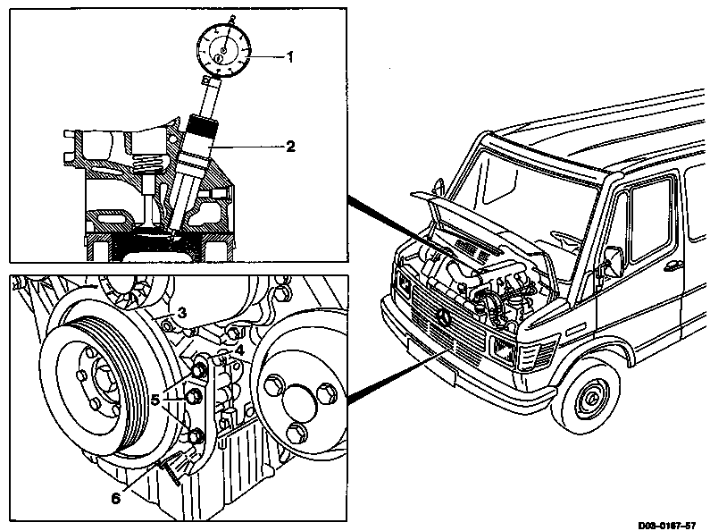
1 | Dial gauge |
2 | Measuring device |
3 | Vibration damper |
4 | TDC sensor bracket |
5 | Hexagon bolts 10 Nm |
6 | Pin |
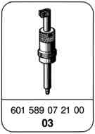
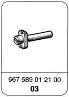
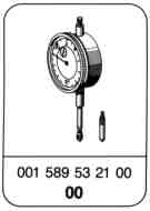
Special tools
Checking
-------------------------------
Note
The setting of the TDC sensor bracket must be checked:
a) When replacing the TDC sensor bracket.
b) When replacing the crankshaft, the hub or the vibration damper.
c) When adding parts to short engines.
d When replacing or installing the timing case cover.

1 Position piston of cylinder 1 to approx. 10° before ignition TDC.
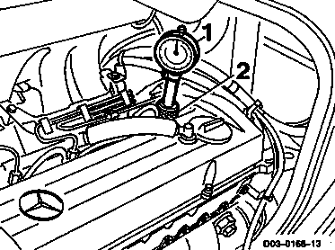
2 Screw measuring device (2) into the
precombustion chamber bore and fit on dial
gauge (1) with a preload of 5 mm.
1 001 589 53 21 00
2 601 589 07 21 00
3 Slowly rotate crankshaft in direction of rotation of engine until the large pointer of the dial gauge stops (TDC position).
4 Slacken dial gauge and once again fit on with a preload of 5 mm.
5 Set dial gauge to zero.
6 Slowly rotate crankshaft further in direction of rotation of engine until the dial gauge has moved back 3.65 mm.
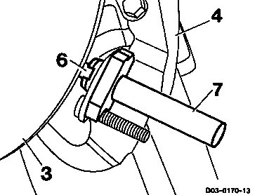
7 Insert fixing device (7) into the TDC sensor bracket (4).
Note
The pin (6) on the vibration damper (3) should engage in the slot of the fixing device (7).
7 667 589 01 21 00
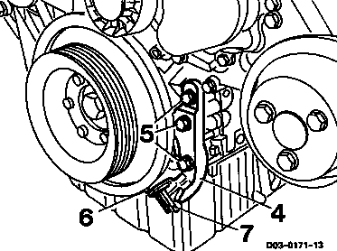
8 If the pin does not engage:
8.1 Slacken hexagon bolts (5) and move the TDC sensor bracket (4) sufficiently until the pin (6) engages.
8.2 Screw hexagon bolts (5) tight, 10 Nm.
9 Remove fixing device (7) from the TDC sensor bracket.
10 Take off dial gauge and unscrew measuring device from the precombustion chamber.