01-417 Removal and installation of precombustion chambers
Preceding work: Mount for engine control removed (30-300). Nozzle holders removed (07.1-230). | Operation no. of operation texts and work units or standard texts and flat rates 01-5412 |


Angular injection
(example engine 601)
Vertical injection
(example engine 601)
P01-0135-13
P01-0134-13
Glow plugs (R9) | screw out, screw in, 20 + 2 Nm (step 1). |
Vertical injection: | |
Threaded ring (112) | screw out, screw in, 100 Nm, When screwing in or out assure that the pin wrench is seated in the grooves in the threaded ring. |
Angular injection: | |
Threaded ring (112a) | screw out, screw in, 130 Nm, splined wrench |
Precombustion chamber (110) | knock out, install, impact puller Note |
Precombustion chamber mounting bore | in cylinder head, clean, check and cover Note |
Precombustion chamber survey
Engine | 601.91 1) 602.91 1) 603.91 1) | 603.96 up to 9/88 | 601.91 as of 10/86 up to 8/88 | 602.961 up to 09/88 | 601.91 2) 602.91 2) 603.91 2) as of 09/88 | 602.961 as of 09/88 602.962 Standard 602.96 as of 1989 603.96 as of 09/88 | 603.962 2) 603.970 2) as of 09/88 603.9713) as of 09/92 as of 04/94 602.96/ 603.966) 603.976) |
Code | 601/07 | 601/09 | 601/14 | 601/15 | 601/25 or 295) | 601/26 | 601/30 |
Version | A | A | B | B | C | C | C |
Combustion neck OD (mm) | 14 | 15 | 14 | 15 | 14 | 15 | 15 |
1) Without exhaust gas recirculation
2) With exhaust gas recirculation starting 02/89
3) As of 02/92 , ECE as of 01/93, certain burner bores countersunk 4°, prechamber volume increased to 11.37 cm3
4) Engine 602.96 as of 05/92 with EGR, certain burner bores countersunk 4°
5) As of 03/92 with EGR
6) As of 04/94 all turbocharged engines, (standard prechamber of 11. 37 cm3) prechamber volume and certain burner bores countersunk 4°


Differentiation, vertical and angular injection
P01-0111-17
P01-0112-17
A Precombustion chamber, vertical injection B Precombustion chamber angular injection, inclined 5°
Code 601/07, 601/17, 601/09, 601/23 Code 601/14, 601/15
x | Cone |
y | Recess |

C Precombustion chamber, angular injection
Inclined 5°, turned 180°
Code 601/25, 601/26, 601/30/36
x Cone
y Recess
P01-0113-17

Differentiation, combustion neck diameter
The individual combustion neck diameters (d) differ on naturally aspirated engines and turbo-engines.
d=14 mm naturally aspirated engines
d=15 mm turbo-engines
P05-0130-15

Differentiation, combustion bores
6 combustion bores with different diameters are located in different planes and at different angles in the bottom section of the precombustion chamber (combustion neck).
The injection angle is 180°, on engine 602.61, 603.971 - 164°.
P01-0136-15
Combustion bore diameters (dia. in mm)
Precombustion chamber code | 601/07 or 17 | 601/09 or 23 | 601/14/25 | 601/15/26 | 601/30 |
H Firing duct J Combustion neck K Combustion bore L Combustion bore M Combustion bore N Combustion bore O Bore for glow plug | 7.0 14.0 1.5 3.2 3.0 2.0 10.0 | 7.0 15.0 1.5 3.2 3.0 2.0 10.0 | 7.0 14.0 1.8 3.0 3.0 2.5 10.0 | 7.0 15.0 1.8 3.0 3.0 2.5 10.0 | 7.0 15.0 1.8 3.0 3.0 2.5 10.0 |
Tightening torques Nm
Glow plugs | 20+2 |
Threaded ring, vertical injection | 100 |
Threaded ring, angular injection | 130 |


Special tools
615 589 00 07 00
603 589 00 09 00
602 589 00 33 00
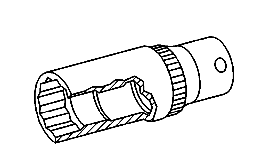


001 589 65 09 00
001 589 72 21 00
001 589 66 21 00

Removal, installation
-------------------------------
1 Screw out glow plugs (R9).
Installation note
Tightening torque 20 + 2 Nm.
P01-2465-13

Vertical injection:
2 Screw threaded end (03) of pin wrench
615 589 00 07 00 into threaded ring of precombustion chamber.
P05-2132-13

2.1 Slide sleeve (02) of pin wrench over thread-
ed end and insert into grooves in threaded ring.
The sleeve must be seated tightly in the grooves of the threaded ring.
2.2 Counter sleeve (02) with hex. head bolt (01).
P05-2133-13
2.3 Screw out threaded ring with open-end wrench on hex. end of sleeve (02).
Installation note
Oil threaded ring.
Tightening torque 100 Nm.

Angular injection:
3 Screw out threaded ring with splined wrench 603 589 00 09 00.
Installation note
Oil threaded ring.
Tightening torque 130 Nm.
P01-2235-13

4 Screw impact puller 602 589 00 33 00 into precombustion chamber and knock out precombustion chamber.
P01-2236-13

Installation note
Insert precombustion chamber into mounting bore so that lug on collar of precombustion chamber fits in recess in cylinder head (arrows).
5 Clean mounting bore for precombustion chamber in cylinder head, check and cover.
P01-2199-13
Note
Refinish precombustion chamber sealing surface if required (01-410).
6 Check precombustion chambers.
Note
The spherical pin must not be burned or scaly.
If the combustion tips are burned or cracked in the bottom section of the precombustion chamber, check the following:
1. Oil level at oil temperature of approx. 80°C. If the quantity of oil in the oil pan is too high, correct oil level.
2. Check piston vacuum pump for damage or replace vacuum box on injection pump.
Which of the two components is unfit for use can be seen on the vacuum lines (blackened with oil).
7 Install in opposite order.