


001 589 49 21 00
Torque meter
741 589 01 63 00
Pressing-on tool
717 589 00 31 00
Retainer wrench
741 589 02 21 00
Measuring device

741 589 00 43 00
Insertion tool

1 | Insert determined spacer disk into mounting hole for inner bearing shell. |
The chamfered side of the spacer disk must face toward the mounting hole. |
2 | Insert inner bearing shell into rear axle housing (1). |
Align inner bearing shell parallel to mounting hole. New inner bearing shells may not be oiled or cleaned, and they must be installed in the supplied condition. |
3 | Draw inner bearing shell into rear axle housing (1) using insertion device (01). |
4 | Check contact surface of inner bearing shell on rear axle housing (1) using feeler gauge (thickness 0.05 mm). |
The inner bearing shell must be fitted flush to the mounting hole in the rear axle housing (1). |
P35.31-2304-03

5 | Insert drive pinion (2) into rear axle housing (1). |
6 | Attach installer tool (04) to rear axle housing (1) and position spindle at centering bore of drive pinion (2). |
7 | Fix drive pinion (2) with spindle into place in inner bearing shell. |
D35.30-A002-06

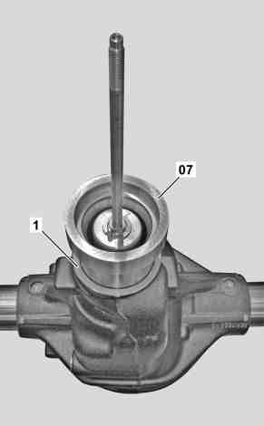
8 | Prepare threaded rod (05), pinion support (06) and housing support (07) from measuring device. |
9 | Attach threaded rod (05) to pinion support (06). |
10 | Screw pinion support (06) with threaded rod (05) finger-tight onto drive pinion (2). |
11 | Install housing support (07) in rear axle housing (1). |
D35.30-A003-03
D35.30-A004-03


12 | Prepare dial indicator (08) and punch (09) from measuring device. |
13 | Install outer bearing shell (3). |
14 | Insert dial indicator (08) into punch (09) and set a pretension of 3.5 mm. |
15 | Position punch (09) with dial indicator (08) onto tapered roller bearing (4) and calibrate dial indicator (08) to zero. |
The calibration procedure for the dial indicator (08) must be made on the measuring plate. |
P35.31-2307-03
P35.31-2308-03


16 | Prepare support disk (010) from measuring device. |
17 | Position punch (09) with dial indicator (08) and tapered roller bearing (4) on pinion support (06). |
Make sure that the dowel pin (5) of the pinion support (06) engages in the bore (6) of the punch (09). |
18 | Insert support disk (010). |
P35.31-2309-03
P35.31-2310-03


19 | Prepare force applicator (011) with toggle (012) from measuring device. |
20 | Screw force applicator (011) with spring onto threaded rod (05). |
The toggle (012) must be in the uppermost position during assembly, to prevent any spring pretension. |
Drive pinion (2) must be held securely when screwing on force applicator (011). |
D35.30-A005-03
D35.30-A006-03
21 | Turn toggle (012) with zero clearance up against spring. |
Note the deflection of the number value, caused by rotation of the toggle (012) on the dial indicator (08). The deflection intensity initially stays at a constant level and drops off suddenly after several turns. At this particular moment, the free play of the spring is reached and the toggle (012) may then no longer be turned. |
Also ensure free play through upward and downward movement of spring. |
22 | Turn toggle (012) through 14 turns clockwise. |
23 | Turn entire body at hexagon (arrow a) 10 turns clockwise. |
This serves to ensure that the outer bearing shell (3) is correctly seated. |
24 | Turn toggle (012) through another 14 turns clockwise. |
25 | Determine each highest and lowest measurement value by turning entire body. |
To do so, red off measurement value on dial indicator (08) and note down. |
26 | Calculate mean value. |
The mean value is determined by adding the highest and lowest measurement value and then dividing their sum by two. |
27 | Calculate thickness of shim (7). |
The shim thickness is calculated by adding the specified correction value and the mean value. |
28 | Remove all special tools. |
29 | Remove drive pinion (2). |
30 | Install outer bearing shell (3) using a suitable drift. |
Align the outer bearing shell (3) parallel to the mounting hole. The new outer bearing shell (3) may not be oiled or cleaned and must be installed in the supplied condition. |
31 | Install drive pinion (2) and fix in place with spindle. |
To do so, install the drive pinion (2) without zero clearance. |
32 | Insert determined shim (7). |


33 | Insert tapered roller bearing (4). |
34 | Drive in old drive flange (8) without radial shaft sealing ring using suitable sleeve and rubber hammer until collar nut can be screwed on. |
35 | Screw on collar nut by hand. |
P35.31-2314-03
P35.31-2315-03

36 | Mount retainer wrench (013) onto old drive flange (8). |
37 | Tighten collar nut to specified torque . |
38 | Turn old drive flange (8) by 5 turns clockwise, then retighten again to torque . |
39 | Remove retainer wrench (013). |
D35.30-A007-11

40 | Determine friction value with torque meter (014) and compare with specified value. |
If the measured value is outside the tolerance range, | |
| |
repeat entire procedure. |
41 | Remove old drive flange (8). |
If the measured value is inside the tolerance range. |
D35.30-A008-03