
P35.20-2004-06
Shown on model 220 with AIRMATIC
4 Tie rod
4a Cam bolt
4b Rubber bushing
4c Tie rod joint
| Remove/install | ||
| Notes on self-locking nuts and bolts | All models | |
Danger! | Risk of death caused by vehicle slipping or toppling off of the lifting platform. | Align vehicle between the columns of the lifting platform and position the four support plates at the lifting platform support points specified by the vehicle manufacturer. | |
1 | Raise vehicle | ||
2 | Press track rod joint (4c) out of wheel carrier | ||
| |||
Thrust piece | |||
Puller | |||
3 | Remove track rod (4) from rear-axle carrier | Installation: The rear axle shaft must be horizontal when tightening the tie rod nut on the rear axle carrier. Installation position: mark position of cam bolt (4a) in relation to rear-axle carrier (arrow). | |
| |||
Screwdriver bit | |||
| Checking | ||
4 | Inspect track rod rubber mount (4b) | If necessary after checking: | |
Remove rubber mount of tie rod. | |||
Extraction and insertion tool | |||
Remove/install eccentric rubber mount of tie rod | |||
Extraction and insertion tool | |||
5 | Install in the reverse order | ||
6 | Adjust rear-axle toe | Models 215, 220 without maximum security package, code Z07 | |
Model Series 220 with maximum security package, Code Z07 |
Tie rod
Number | Designation | Model 215 | Model 220 | |||
BA35.20-P-1001-04A | Self-locking nut, track rod to rear axle carrier | Stage 1 | Nm | 70 | 70 | |
Stage 2 | ° | - | - | |||
BA35.20-P-1002-04A | Self-locking nut, tie rod at wheel carrier | yellow M101 | Nm | - | - | |
silver or blue M101 | Nm | - | - | |||
silver or blue M101.5 | Stage 1 | Nm | 30 | 30 | ||
Stage 2 | ° | - | - | |||

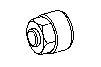


140 589 00 33 00
Screwdriver bit
Puller
Thrust piece
Removal and installation tool
201 589 05 63 00
119 589 00 10 00
220 589 00 43 00