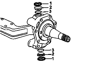
Steering bar arm bolt and connection to the front axle
BA33.25-B-1003-01A
Shaft end
Number
Designation
Front axle 732.715/716
Front axle 732.717/723
BE33.25-B-1003-01A
Axial play and compensating washers
Beam handle
mm
0,01...0,15
0,01...0,15
Washers thickness
mm
1,7...2,5
0,7...2,3
Shaft end
Number
Designation
Front axle 732.702, 732.704, 732.718/719, 732.732/733, 732.736, 732.740/741, 732.748
Front axle 732.759
BE33.25-B-1003-01A
Axial play and compensating washers
Beam handle
mm
0,01...0,15
0,01...0,15
Washers thickness
mm
0,7...2,5
0,7...2,3
Shaft end
Number
Designation
Front axle 732.793
BE33.25-B-1003-01A
Axial play and compensating washers
Beam handle
mm
0,01...0,15
Washers thickness
mm
1,7...2,5
Steering knuckle
Number
Designation
Front axle 733.894/895/861
BE33.25-B-1003-01D
End play and compensating washers
Steering knuckle end play
mm
0,01 ... 0,15
Washers thickness
mm
1,7 ... 2,8
Shaft end
Number
Designation
Front axle 732.715/716
Front axle 732.717/723
BE33.25-B-1004-01A
Beam handle temperature for king pin assembly
° C máx
150
150
Shaft end
Number
Designation
Front axle 732.702, 732.704, 732.718/719, 732.732/733, 732.736, 732.740/741, 732.748
Front axle 732.759
BE33.25-B-1004-01A
Beam handle temperature for king pin assembly
° C máx
150
150
Shaft end
Number
Designation
Front axle 732.793
BE33.25-B-1004-01A
Beam handle temperature for king pin assembly
° C máx
150
Steering knuckle
Number
Designation
Front axle 733.894/895/861
BE33.25-B-1004-01D
Beam handle temperature to assemble the master pin
°C máx
150
Axle body, steering knuckle
Number
Designation
Front axle 732.7
Front axle 733.894/861
BA33.25-B-1003-01A
Steering bar arm bolt and connection to the front axle
M16x1.5 N 14115
Nm
-
-
M16x1.5 EN 28676
Nm
-
-
M16.5 x 1.5 MBN 10105
Nm
-
-
M18x1,5 10.9
Nm
380
-
M20x1,5 10.9
Nm
540
540
M22x1,5 10.9
Nm
720
-
M24x1,5 10.9
Nm
920
-
383 589 00 61 00
Guide pin
343 589 01 61 00
Centering pin
346 589 00 63 00
Supercooler box
321 589 12 33 00
Pressing-out tool
Remove
1
Remove the nut and washer (1) from the lock screw on the beam cuff.
2
Remove the lock screw with the help of an appropriate punch.
B33.25-0060-01
3
Remove the lock rings (1) upper and lower.
4
Remove the covers (2) and the top and bottom sealing rings (3).
B33.25-0020-01
5
Remove the kingpin with the aid of the device (1), the extender (2, ) and the hydraulic jack (3).
B33.25-0024-01
Install
6
Install on the beam cuff (3) the shaft end (1) and adjust the axial play through compensating washers (2).
B33.25-0022-01
7
Centralize the shaft end (1) with the thrust bearing and the compensating washer selected on the beam cuff (2), with the guide mandrel (3). Front axle 733.861/894 Front axle 732.7 Mandrel VL 3/35 and VL 3/6, 7 - 383 589 00 61 00 ø 38 mm Mandrel VL 3/37 - 343 589 01 61 00 ø 45 mm
B33.25-0023-01
8
Cool the kingpin with liquid nitrogen, using the cooling box. Front axle 733.861/894 Front axle 732.7
If you cannot cool the kingpin, you can heat the beam cuff with a heat gun. Do not exceed the temperature of 150° to avoid damaging the sealant. The kingpin as the beam cuff and the bushings are to be perfectly clean and dry, free of any oily substance.
Use gloves or a magnetic rack to assemble master pin.
9
Inset the kingpin to the groove until it is aligned with the lock screw hole.
10
Mount the lock screw with the milled side facing the master pin and tighten the fixing nut (1). .