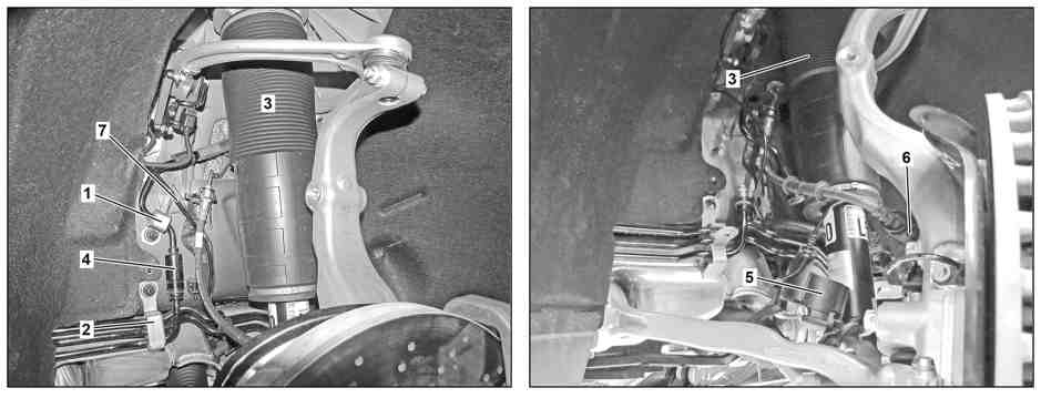
P32.25-2319-08
Shown on left side of vehicle |
1 | Line bracket | 4 | Quick-release coupling | 7 | Electric line | ||
2 | Line bracket | 5 | Cable duct | ||||
3 | Suspension strut | 6 | Brake hose clip |

Shown on left side of vehicle |
3 | Suspension strut |
8 | Spring control arm |
9 | Suspension strut ball joint |
10 | Puller |
11 | Thrust piece |
P32.25-2320-11

P32.25-2321-08
Shown on model 222 |
15 | Covers | 17 | Cover | ||||
16 | Electrical connector | 18 | Nuts |
Danger | Risk of death caused by vehicle slipping or toppling off during lifting | Only lift vehicle at the lift support points specified by the vehicle manufacturer. | |
Danger | Risk of death caused by vehicle slipping or toppling off of the lifting platform. | Align vehicle between vehicle lift columns and position the four support plates at the vehicle lift support points specified by the vehicle manufacturer. | |
Topical note | Notes on self-locking nuts and bolts | ||
Notes on Active Body Control suspension | |||
Notes on repair work on suspension components | |||
| Remove/install | ||
1 | Release pressure in ABC system using diagnostic system | ||
| |||
Warning | Risk of injury caused by fingers being jammed or pinched when removing, installing or aligning hoods, doors, trunk lid/rear-end door or sliding roof. | No parts of the body or limbs should be within the operating area when the components are moving. | |
2 | Open and secure engine hood | ||
3 | Detach corresponding front complete wheel | ||
4 | Detach line bracket (1) | ||
5 | Unscrew nut and open line bracket (2) | When removing the left suspension strut (3) | |
Warning | Risk of injury to skin or eyes from hydraulic fluid spraying out under pressure.Risk of poisoning from swallowing hydraulic fluid. | Depressurize hydraulic system completely before starting any work on it. Wear protective clothing and safety glasses. | |
6 | Disconnect hydraulic line from quick-release coupling (4) and seal lines using suitable stop plugs | ||
Record plug | |||
Detaching tool | |||
7 | Open cable duct (5) on suspension strut (3) and place to one side | ||
8 | Detach brake hose clip (6) from steering knuckle | ||
9 | Unhook electrical line (7) from bracket on longitudinal member | ||
10 | Unscrew nut from suspension strut (3) on spring control arm (8) | | |
Nut, front suspension strut to spring control armNut, suspension strut at front to spring control arm | |||
11 | Detach suspension strut (3) from suspension strut joint (9) using puller (10) and thrust piece (11) | | |
To pull off the right suspension strut (3), turn the steering to the left. To pull off the left suspension strut (3), turn the steering to the right. | |||
Puller | |||
Thrust piece | |||
12 | Remove corresponding covers (15) from suspension strut tower | ||
13 | Detach electrical connection (16) from corresponding suspension strut (3) | ||
14 | Detach corresponding cover (17) and place to one side | ||
15 | Unscrew nuts (18) from corresponding suspension strut (3) | Nut, suspension strut to bodyNut, suspension strut at front to body | |
16 | Support steering knuckle using telescopic lifter and transmission plate | ||
| 000 588 10 62 00 Support plate | ||
| 000 588 11 62 00 Major assembly mount | ||
17 | Secure steering knuckle against folding down | ||
18 | Detach transverse control arm from steering knuckle | ||
19 | Lower telescopic lifter far enough to enable suspension strut (3) to be removed | | |
| Check | ||
20 | Check suspension strut (3) condition | When reinstalling suspension strut (3) | |
If damaged or worn | |||
| |||
Replace suspension strut (3) | |||
Dispose of the damaged suspension strut (3) correctly. | |||
21 | Check condition of suspension strut joint (9) on spring link (8) | In the event of play or damage | |
| |||
Replace spring link (8) | |||
22 | Install in the reverse order | ||
23 | Fill and bleed ABC system | ||
24 | Calibrate stroke of suspension struts (3) | ||
| |||
Whenever a suspension strut is replaced, calibration using the diagnostic system must be performed in the menu "Control units - Adaptation / Teach-in processes". |


216 589 00 34 00
Thrust piece
221 589 01 33 00
Detaching tool
601 589 04 33 00
Puller
129 589 00 91 00
Record plug