
Show on model 204.057 |
3 | Heat shield |
4 | Electrical line, terminal 30 |
5 | Heat shield |
6 | Mounting clip |
7 | Electrical line |
8 | Electrical line, terminal 50 |
9 | Retaining clips |
M1 | Starter |
P15.30-2211-06
Danger | Risk of death caused by vehicle slipping or toppling off of the lifting platform. | Align vehicle between vehicle lift columns and position the four support plates at the vehicle lift support points specified by the vehicle manufacturer. | |
Warning | Risk of injury. Skin or eye injuries may result when handling hot or glowing objects. | Wear protective gloves, protective clothing and safety glasses, if necessary. | |
Caution | Risk of injury caused by scraping or cutting body parts on sharp vehicle parts | Always wear protective gloves when working on or near sharp and non-deburred vehicle parts. | |
Topical note | Information on preventing damage to electronic components due to electrostatic discharge | ||
Topical note | Notes on self-locking nuts and bolts | ||
| Remove/install | ||
1 | Disconnect ground cable at battery |
| |
Topical note | Notes on battery | ||
Engine 276 (except 276.8) in model 207 | |||
2 | Remove front engine cover | Engine 276 (except 276.8) in model 204 (except 204.388/988/990), 207 (except 207.367/388) | |
3 | Remove air filter housing | Engine 276 (except 276.8) in model 204 (except 204.388/988/990), 207 (except 207.367/388) | |
Screw/bolt, air filter to cylinder head cover | |||
Screw/bolt, air filter to air intake pipe support brace | |||
4 | Remove the heat shield (3) at the exhaust manifold | Engine 276 (except 276.8) in model 204 (except 204.388/988/990), 207 (except 207.367/388) | |
5 | Remove lower engine compartment paneling |
| |
Engine 276 (except 276.8) in model 204.9 | |||
6 | Unlock and disconnect the electrical plug connection at the speed-sensitive power steering solenoid valve | Engine 276 (except 276.8) in model 204.388/988/990 | |
7 | Remove steering coupling |
| |
8 | Remove heat shield over engine mount on LH engine support |
| |
9 | Remove the heat shield (5) at the starter (M1) | ||
10 | Pull off the contact protection at terminal 30 and remove the electrical line for terminal 30 (4) at the starter motor (M1) | Nut, connection for terminal designation 30 | |
11 | Unclip the electrical lines (7) at the starter (M1) | Installation: Make sure the retaining clip (6) has been positioned correctly. | |
12 | Remove screws/bolts of starter (M1) | Bolt, starter to crankcase/transmission | |
13 | Remove the starter (M1) from the mount in the crankcase | ||
14 | Unclip the electrical line at terminal 50 (8) on the crankcase | Engine 276 (except 276.8) in model 204 (except 204.388/988/990), 207 (except 207.367/388) | |
Installation: Make sure the retaining clips (9) have been positioned correctly. | |||
15 | Remove the electrical line for terminal 50 (8) at the starter motor (M1) | Nut, connection for terminal designation 50 | |
16 | Remove starter (M1) from below | ||
17 | Check ring gear at the drive plate for wear and damage | Rotate engine at center Bolt, crankshaft in the direction of engine rotation. | |
Socket wrench bit | |||
If wear or damage present | |||
| |||
Replace drive plate. | |||
18 | Install in the reverse order |
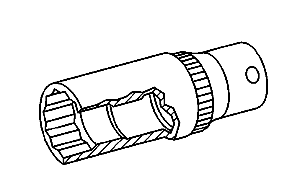
001 589 65 09 00
Socket wrench bit