AR14.00-P-5303AB | Remove/install an oxygen sensor | 25.1.12 |
ENGINE 112.923 in MODEL 129.059
ENGINE 112.943 in MODEL 129.064
ENGINE 113.961 in MODEL 129.068
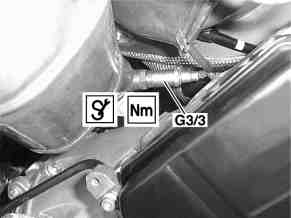
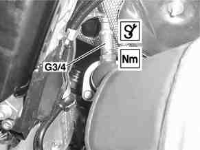
P14.00-2007-01
Diagram left
G3/3 Left O2 sensor upstream of TWC
Diagram right
G3/4 Right O2 sensor upstream of TWC
P14.00-2008-01
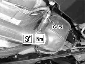
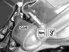
P14.00-2009-01
Diagram left
G3/5 Left diagnosis sensor downstream of TWC
Diagram right
G3/6 Right diagnosis sensor downstream of TWC
P14.00-2010-01
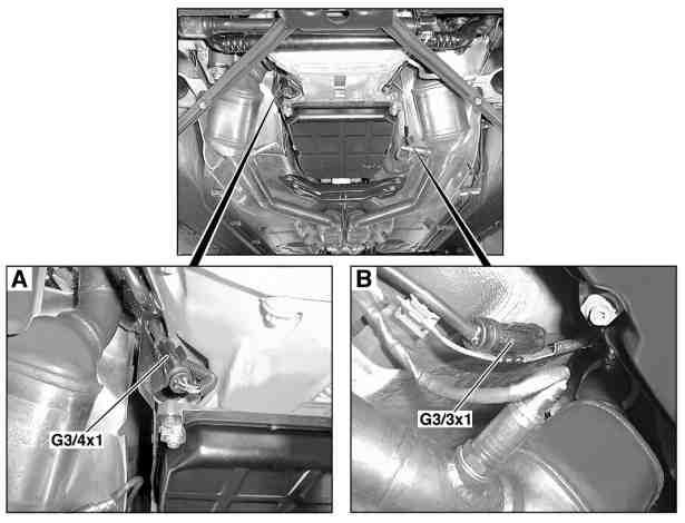
P14.00-2006-06
Fig. A
G3/4x1 Connector for right O2 sensor upstream of TWC
Fig. B
G3/3x1 Connector for left O2 sensor upstream of TWC
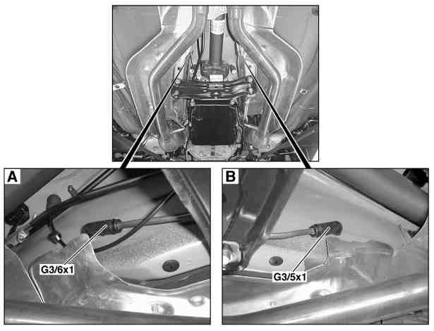
P14.00-2005-06
Fig. A
G3/5x1 Connector of right diagnostic sensor downstream of TWC
Fig. B
G3/6x1 Connector of left diagnostic sensor downstream of TWC
Modification notes
10.11.04 | Value changed from 55 Nm to 45 Nm | Value in Series 1001 for engine 112.910/911/ |
Fig. item etc. | Work instructions | ||
G3/3, G3/4 G3/5, G3/6 | Oxygen sensor Diagnostic sensor | Installation: Coat thread on oxygen sensor and diagnostic sensor with heat-resistant lubricant | |
| |||
| |||
G3/3x1, G3/4x1 | Oxygen sensor connector | left / right upstream of TWC | |
G3/5x1, G3/6x1 | Diagnostic sensor connector | left / right downstream of TWC |
O2 sensor
Number | Designation | Engines 112.910/911/ | Engines 113.940/941/ | |
BA14.00-P-1001-01A | O2 sensor on exhaust pipe/ exhaust manifold | Nm | 45 | 55 |
Repair materials
Number | Designation | Order number |
BR00.45-Z-1005-06A | Paste, hot lubrication 1 kg, DB supply specification 6879.20 | A 000 989 76 51 |

000 589 71 03 00
Box wrench bit, Delco R4 and A6