


606 589 00 37 00
119 589 00 43 00
Drift punch
Pliers
111 589 25 61 00
111 589 00 91 00
Case
Connector

S05.30-3005-01
1 Screw the connector (1) into the sparkplug housing hole and insert pressure into the compression chamber (min. 5 bar)
Only if cylinder head installed. Use assembly board if cylinder head removed.
2 Fit the guide sleeve (3) into the cylinder head and screw and align the bracing tool (2) in the cylinder head

S05.30-3006-01
3 Assemble the lever thrustor (5)
4 Place the assembly cartridge (4) inside the guide sleeve (3), hook the lever (5) in the bracing tool (2) and rest it lightly on the two bearing bolts of the assembly cartridge (4).
5 Apply slight pressure to the lever thrustor (5) and at the same time slowly turn the knurled screw of the assembly cartridge (4) to the right (arrow) until it is felt to fit properly into the gap of the valve collets.

S05.30-3007-10
6 Press lever thrustor (5) down as far as a stop (arrow). After this, exert slight pressure with your finger on the knurled screw of the assembly cartridge (4) (arrow).
Lever thrustor (5) should press as vertically as possible (sectional view) on the assembly cartridge (4) in order to avoid the assembly cartridge (4) jamming. Should the travel of the lever of the thrustor (5) not adequate, the clearance to the cylinder head can be enlarged by inserting the bracing tool (2).
7 Slacken assembly cartridge (4) and lever thrustor (5) and take off. The valve cotters are removed automatically.

S05.30-3008-01
8 Check if the valve cotters (6) are in the assembly cartridge (4), repeating, if required, work steps 4 through 7.

S05.30-3009-01
9 Remove the guide sleeve (3), the upper plate of the valve spring (7) and the valve spring (8).

S05.30-3010-01
10 Take out the valve rod retainer (1) with pliers (9).
11 Remove the lower plate of the valve spring checking if there are any marks; if required, change it and install it again.

S05.30-3011-01
12 Fit the protective cover (11) (included in the set of parts) onto the valve rod.
13 Place a new retainer (10) in the valve rod and press on with the drift punch (12).
14 Remove the protective cover (11)
S05.30-3009-01
15 Install valve spring (8) and valve spring plate (7) in the upper part.
16 Fit the guide sleeve (3) in the cylinder head.
S05.30-3012-01
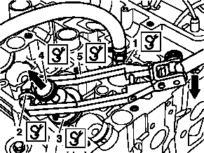
17 Install the assembly cartridge (4) with the valve cotters inserted in the guide sleeve (3) hook the lever (5) into the bracing tool (2) and slightly rest on the two bearing bolts of the assembly (4) cartridge (4).
18 Press down lever thrustor (5) as far as a stop (arrow). After this, pull the knurled screw of the assembly cartridge (4) up (arrow) and at the same time slacken the lever thrustor. The valve cotters are installed automatically.
19 Remove all the special tools from the cylinder head except the pressurised air connection with the connector (1).

S05.30-3013-01
20 Check if the valve cotters (6) are well installed, repeating work steps 2 through 8 and 17 to 19 if required.
21 Remove the pressurised air connection from the cylinder head with the connector.