41-085 Measuring propeller shaft alignment with mechanical propeller shaft articulation angle meter
|
Models 5124/201 |
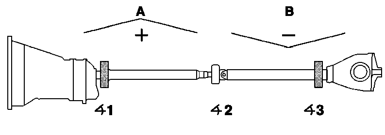
Figure 1
A Positive angle
B Negative angle
1 Difference: Transmission - front propeller shaft
2 Difference: Front - rear propeller shaft
3 Difference: Rear propeller shaft - rear axle center piece assembly
P41-5035-53
Vehicle | Must be on its wheels during the measurement. |
Engine compartment lining or engine |
|
Transmission | Measure and note absolute angle on transmission. Measuring socket for manual transmission 140 589 30 63 00, automatic transmission 140 589 31 63 00, gauge length 140 589 11 21 00 (items 4 - 8). |
Front propeller shaft | Measure and note absolute angle of the front propeller shaft. Measuring socket 140 589 30 63 00, gauge length 140 589 11 21 00 (items 9 - 10). |
Articulation angle ( 1) | Calculate from measured absolute angle on transmission to front propeller shaft, correct if necessary (item 10, example, table). |
Rear propeller shaft | Measure and note absolute angle of the rear propeller shaft. Measuring socket 140 589 30 63 00, gauge length 140 589 11 21 00. |
Articulation angle ( 2) | Calculate from measured absolute angle of the front to the rear propeller shaft, correct if necessary (item 11, example, table). |
Rear axle | Measure and note absolute angle of rear axle housing. Measuring socket 140 589 32 63 00, gauge length 140 589 11 21 00. |
Articulation angle ( 3) | calculate from measured absolute angle of the rear propeller shaft to the rear axle housing, correct if necessary (items 12 - 14, example, table). |
Permitted tolerances of articulation angle ranges
Model | Articulation angle | ||
front ( 1) | center ( 2) | rear ( 3) | |
1241), 201 | - 0°30 - +0°40 | +0°10 - +1°00 | - 0°50 - - 0°10 |
1) On model 124 with 3450 mm wheel base and 3-piece propeller shaft:
front - 0° 40' - + 0° 50'; front propeller shaft to intermediate shaft - 0° 50' - + 0° 00'; intermediate shaft to rear propeller
shaft - 0°00' -+ 1°10' and rear - 1°00' - 0°10'.
On model 124 with 3600 mm wheel base and 3-piece propeller shaft:
front -0°30' - + 0°40; front propeller shaft to intermediate shaft 0°20' - + 0°30'; intermediate shaft to rear propeller shaft -0°20 - + 0°30' and rear 1°00 - 0°10'.
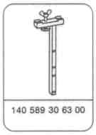


Special tools
Note
On vehicles which are subject to complaint due to drive line vibrations or rough spots during acceleration, the cause can be a deviation of the propeller shaft articulation angle from the specified value. Before determining the articulation angle it is to be ensured that the transmission mount and the exhaust system are not deformed by improper fastening; eliminate deformation, if necessary.

Measurement
1 Vehicle must be on its wheels during the measurement.
Hinweis
Start on the transmission end on the articulation angle measurement. The absolute angles are always read off from the left side of the gauge length.
2 Remove, install engine compartment lining or engine encapsulation.
Measurement of absolute angle on manual transmission
3 Fasten measuring socket (010a) 140 589 30 63 00 with gauge length (010 b) 140 589 11 21 00 on left bearing surface of the transmission with thumb screw and knurled nut (010 c).
P41-5043-13

4 Read off and note measured absolute angle (e.g. 1° 55').
5 Detach measuring socket on transmission.
P41-5044-13

Measurement of absolute angle on autom. transmission
6 Place measuring socket (010 c) 140 589 31 63 00, with gauge length 140 589 31 63 00 attached, on the bearing surfaces (arrows) of the transmission.
Location of bearing surface on transmission housing.
P41-5046-13

7 Read off and note measured absolute angle.
Location with measuring socket and gauge length
P41-5045-13

All vehicles
8 Fasten gauge length to the two upper tapped holes of the measuring socket 140 589 30 63 00 (arrow, except for models 124 with engine 111 and 124 034/036).
9 Position measuring socket (010 a) on the front propeller shaft. Read off and note absolute angle (e.g. 2° 10').
Note
Ensure that the prism of the measuring socket fits accurately on the propeller shaft tube and not on a balance weight.
P41-5048-13

Models 124 with engine 111 and 124.034/036
Fasten gauge length to the two lower tapped holes (arrows) and perform measurement.
P41-5047-13

All vehicles
10 Position measuring socket 140 589 30 63 00 with gauge length on the rear propeller shaft and read off and note absolute angle (e.g. 2° 45').
P41-5049-13

11 Clean remains of paint and sealing compound of the bearing surfaces (arrows) on rear axle housing and remove material irregularities using a suitable tool.
P41-5050-13

13 Position measuring socket (010 d) 140 589 32 62 00 with gauge length on rear axle housing. Read off and note absolute angle (e.g. 2° 40').
13 Using the measured absolute angles, calculate the articulation angle in accordance with the example and correct if necessary (see example).
P41-5054-13

Example
The calculated articulation angles resulting at the "front" from the transmission to front propeller shaft ( 1), at the "center" from the front to rear propeller shaft ( 2) and "rear" from the rear propeller shaft to rear axle center piece assembly ( 3).
P41-5053-53

14 By means of the calculated articulation angle on the example the front and center articulation angle ( 1 and 2) is within the tolerance. The rear articulation angle ( 3), is changed by inserting a 2 mm shim between the rear axle housing and rubber mount in addition to the existing shim (arrow). Refer to table: Permissible tolerances of articulation angle ranges.
P41-5052-13
Repair notes:
The positive angle (+) results when the absolute angle measured first is less than the angle measured next (refer to example). The reverse applies to the negative angle (-). The articulation angle is changed by inserting shop-made shims at the transmission cross member and the propeller shaft intermediate bearing (refer to drawings). Shims of 1-4 mm thickness are available at the rear axle (refer to parts microfiche).
A correction of 1 mm at the transmission cross member, rear engine mount, or propeller shaft intermediate mount produces a change in articulation angle of approx. 0° 10' and of 0°15' - 0°20' at the front rear axle center piece assembly mounting. The bolt length is to be extended by 5 mm when using shims with a thickness > 2 mm. If a shim of > 5 mm thickness is required, the rubber mounts of the engine/transmission mounting and the front mounting of the rear axle are to be checked for signs of settling or wear and replaced, if necessary.

The aim is to keep all articulation angle deviations in the middle tolerance band.
The shims for lowering the transmission cross member are to be shop-made depending on the calculated thickness by means of the following drawings. Shim material: steel or aluminium.
On models 124.034/036, the articulation angle is to be compensated for using four large body washers (part no. 124 990 48 40) between the transmission cross member and frame floor (arrows).
P41-5051-13

Shop-made shims for transmission cross member
Model 124 with engines 103, 104,
603 and manual transmission
P41-5056-13

A Model 124 with engines 102, 103, 111, 601, 602 with automatic transmission
B Model 124 with engines 102, 111, 601, 602 with 4- and 5-speed manual transmission
Model 201 with engines 102, 601,
602 with 4-speed manual
transmission
P41-5037-13

A Model 201 with engines 102, 103, 601 and 602 with 5-speed manual transmission
B Model 201 with engine 103 and automatic transmission
P41-5038-13

In the event of complaint, 4 mm or 5 mm thick aluminium shims are to be used for raising the transmission between the rubber mount and transmission cross member for models 124 (except for 124.034/036), and 201 with part no. 116 242 03 26 or 116 242 02 26.
Shims for models 124.034/036 are to be produced in accordance with the drawing depending on the calculated thickness.
A Model 124.034/036 (2 pieces)
P41-5057-13

Only in extremely critical cases should the propeller shaft intermediate bearing be lowered on model 124. The lateral offset of the propeller shaft is made considerably worse due to the inclined installed position of the propeller shaft intermediate bearing.
All models
B Shims between frame floor and propeller shaft intermediate bearing
P41-5042-13