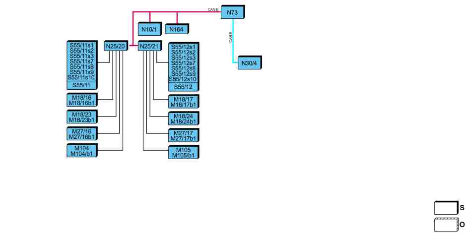
S91.29-A024-79
Illustration shows MODEL 447.8 |
M18/16 | Left 1st rear seat row head restraint inclination adjustment electric motor | N164 | Decoupler CAN control unit | |
M18/16b1 | Hall sensor 1, left 1st rear seat row head restraint inclination adjustment electric motor | S55/11 | Left 1st rear seat row electric seat adjustment switch group | |
M18/17 | Right 1st rear seat row head restraint inclination adjustment electric motor | S55/11s1 | Left 1st rear seat row head restraint height/inclination adjustment switch | |
M18/17b1 | Hall sensor 1, right 1st rear seat row head restraint inclination adjustment electric motor | S55/11s2 | Left 1st rear seat row backrest inclination adjustment switch | |
M18/23 | Left 1st rear seat row head restraint height adjustment electric motor | S55/11s3 | Left 1st rear seat row leg rest switch | |
M18/23b1 | Hall sensor 1, left 1st rear seat row head restraint height adjustment electric motor | S55/11s7 | Left 1st rear seat row memory function button | |
M18/24 | Right 1st rear seat row head restraint height adjustment electric motor | S55/11s8 | Left 1st rear seat row memory 1 button | |
M18/24b1 | Hall sensor 1, right 1st rear seat row head restraint height adjustment electric motor | S55/11s9 | Left 1st rear seat row memory 2 button | |
M27/16 | Left 1st rear seat row backrest inclination adjustment electric motor | S55/11s10 | Left 1st rear seat row seat adjustment starting position button | |
M27/16b1 | Hall sensor 1, left 1st rear seat row backrest inclination adjustment electric motor | S55/12 | Right 1st rear seat row electric seat adjustment switch group | |
M27/17 | Right 1st rear seat row backrest inclination adjustment electric motor | S55/12s1 | Right 1st rear seat row head restraint height/inclination adjustment switch | |
M27/17b1 | Hall sensor 1, right 1st rear seat row backrest inclination adjustment electric motor | S55/12s2 | Right 1st rear seat row backrest inclination adjustment switch | |
M104 | Left 1st rear seat row leg rest inclination adjustment electric motor | S55/12s3 | Right 1st rear seat row leg rest switch | |
M104b1 | Hall sensor 1, left 1st rear seat row leg rest inclination adjustment electric motor | S55/12s7 | Right 1st rear seat row memory function button | |
M105 | Right 1st rear seat row leg rest inclination adjustment electric motor | S55/12s8 | Right 1st rear seat row memory 1 button | |
M105b1 | Hall sensor 1, right 1st rear seat row leg rest inclination adjustment electric motor | S55/12s9 | Right 1st rear seat row memory 2 button | |
N10/1 | Signal acquisition and actuation module (SAM) control unit | S55/12s10 | Right 1st rear seat row seat adjustment starting position button | |
N25/20 | Left 1st rear seat row seat adjustment control unit with memory | CAN B | Interior CAN | |
N25/21 | Right 1st rear seat row seat adjustment control unit with memory | CAN E | Chassis CAN | |
N30/4 | Electronic Stability Program (ESP) control unit | O | Optional | |
N73 | Electronic ignition lock (EZS) control unit | S | Default |
Function requirements, general
No overvoltage or undervoltage
Circuit 15R ON
Seat adjustment of the luxury seats is still possible with the ignition key removed. If "Circuit 15R OFF" status is recognized, the CAN decoupler control unit (N164) bridges the power supply to the left 1st rear seat row seat adjustment control unit with memory (N25/20) and the right 1st rear seat row seat adjustment control unit with memory (N25/21).
Electrical seat adjustment (ESA), general
The ESA enables electrical adjustment of the left 1st rear seat row and right 1st rear seat row. The following adjustment options are available:
Head restraint height
Head restraint inclination
Backrest inclination
Leg rest inclination
Resetting to starting position
In addition, two positions can be stored and called up again.
The ESA includes the following subfunctions:
Function sequence for recording seat position
Function sequence for normalization
Function sequence for antilock device
Function sequence for manual adjustment
Function sequence for storing or retrieving the seat position
Function sequence for seat position in starting position
Function sequence for recording seat position
The electric motors for inclination adjustment are equipped with Hall sensors. Their signals are read in directly by the left 1st rear seat row seat adjustment control unit with memory (N25/20) or the right 1st rear seat row seat adjustment control unit with memory (N25/21) and evaluated. The respective positions of the head restraint, backrest and leg rest are determined by counting the Hall sensor signals during the adjustment procedure.
Additional function requirements for normalization
Circuit 15R ON
The electronic ignition lock (EIS) control unit (N73) sends the circuit status via the interior CAN (CAN B) and CAN decoupler control unit (N164) to the left 1st rear seat row seat adjustment control unit with memory and the right 1st rear seat row seat adjustment control unit with memory.
Function sequence for normalization
Normalization is the basis for recording of the respective seat and head restraint position by the left 1st rear seat row seat adjustment control unit with memory or the right 1st rear seat row seat adjustment control unit with memory. Normalization must be performed during initial startup or in a denormalized condition.
The following mechanical end points must be moved to in order to carry out normalization:
Front end points of backrest inclination
Front end points of head restraint inclination
Front end points of leg rest inclination
Lower end points of head restraint height
To do this, the corresponding button of the left 1st rear seat row electrical seat adjustment switch group (S55/11) or right 1st rear seat row electrical seat adjustment switch group (S55/12) must be pressed for an additional 250 ms after the mechanical end point has been reached. After normalization has been performed, the seat adjustment control unit switches off the corresponding electric motor. During initial startup, normalization is performed using the diagnostic system.
An adjustment is denormalized if no signal is received from the relevant Hall sensor. The denormalization procedure can also be performed using the diagnostic system.
Function sequence for antilock device
If the signal of the corresponding Hall sensor is absent for more than 2 s during an adjustment procedure, this is recognized as blocking and the adjustment procedure is aborted by the seat adjustment control unit. Adjustment in the same direction is not possible until the respective button in the electrical seat adjustment switch group has been released for 2 s. Adjustment in the opposite direction is possible immediately.
Function sequence for manual adjustment
Manual adjustment is performed via the corresponding button of the left 1st rear seat row electrical seat adjustment switch group or the right 1st rear seat row electrical seat adjustment switch group.
An adjustment request from the respective button of the electrical seat adjustment switch group is read in directly by the seat adjustment control unit.
The left 1st rear seat row seat adjustment control unit with memory actuates the following seat adjustment motors directly in accordance with the request:
Left 1st rear seat row head restraint inclination adjustment electric motor (M18/16)
Left 1st rear seat row head restraint height adjustment electric motor (M18/23)
Left 1st rear seat row backrest inclination adjustment electric motor (M27/16)
Left 1st rear seat row leg rest inclination adjustment electric motor (M104)
The right 1st rear seat row seat adjustment control unit with memory actuates the following seat adjustment motors directly in accordance with the request:
Right 1st rear seat row head restraint inclination adjustment electric motor (M18/17)
Right 1st rear seat row head restraint height adjustment electric motor (M18/24)
Right 1st rear seat row backrest inclination adjustment electric motor (M27/17)
Right 1st rear seat row leg rest inclination adjustment electric motor (M105)
Additional function requirements for storing or retrieving the seat position
Respective seat has been normalized
Function sequence for storing or retrieving the seat position
The seat position of the 1st rear seat row is stored by pressing the respective memory function button (S55/11s7, S55/12s7) and the memory 1 button (S55/11s8, S55/12s8) or memory 2 button (S55/11s9, S55/12s9).
The respective seat adjustment control unit reads in the seat adjustment status via a direct line and takes over the "Store seat position" request.
To call up a stored seat position, the respective memory 1 button or memory 2 button must be pressed until the stored seat position is reached.
The respective seat adjustment control unit reads in the seat adjustment status via a direct line and takes over the "Set seat position" request.
Function sequence for seat position in starting position
To call up the starting position of the 1st rear seat row, the respective 1st rear seat row seat adjustment starting position button (S55/11s10, S55/12s10) must be pressed.
The respective seat adjustment control unit reads in the seat adjustment status via a direct line and takes over the "Set starting position" request.