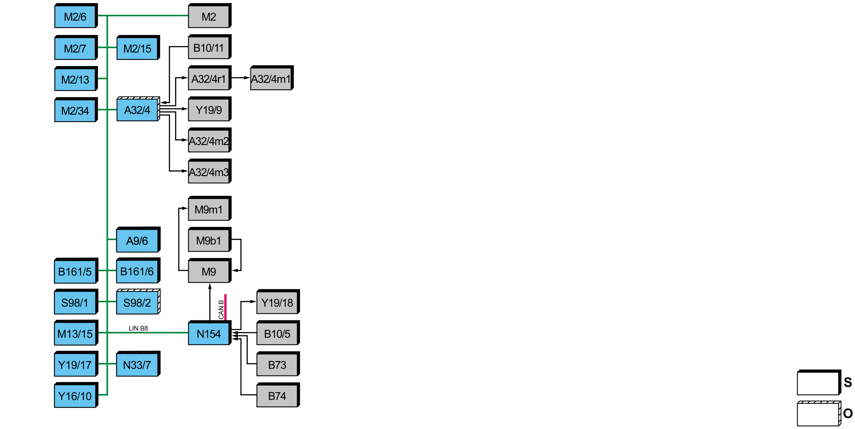
S83.00-A030-79
Climate control regulation, block diagram |
A9/6 | Electric refrigerant compressor | M2/34 | Ram air flap actuator motor | |
A32/4 | Rear heater/air conditioning air recirculation unit (with code HZ7 (Semi-automatically controlled A/C, TEMPMATIC in rear)) | M9 | Blower with interior air temperature sensor | |
A32/4m1 | Rear blower motor (with code HZ7 (Semi-automatically controlled A/C, TEMPMATIC in rear)) | M9b1 | Interior air temperature sensor | |
A32/4m2 | Rear air distribution actuator motor (with code HZ7 (Semi-automatically controlled A/C, TEMPMATIC in rear)) | M9m1 | Blower | |
A32/4m3 | Rear blend air flap actuator motor (with code HZ7 (Semi-automatically controlled A/C, TEMPMATIC in rear)) | M13/15 | Electric auxiliary water pump | |
A32/4r1 | Rear blower regulator (with code HZ7 (Semi-automatically controlled A/C, TEMPMATIC in rear)) | N33/7 | High-voltage PTC heater control unit | |
B10/5 | Evaporator temperature sensor | N154 | Automatic air conditioning (KLA) control unit | |
B10/11 | Rear air conditioning evaporator temperature sensor | S98/1 | Front heater/air conditioning operating unit switch | |
B73 | Left footwell air vent temperature sensor (with CODE HH4 (THERMOTRONIC automatic air conditioning)) | S98/2 | REAR heater/air conditioning operating unit switch (with code HZ7 (Semi-automatically controlled A/C, TEMPMATIC in rear)) | |
B74 | Right footwell air vent temperature sensor (with CODE HH4 (THERMOTRONIC automatic climate control)) | Y16/10 | Condensation prevention switchover valve | |
B161/5 | Cooler pressure and temperature sensor | Y19/9 | Rear A/C evaporator shutoff valve (with code HZ7 (Semi-automatically controlled A/C, TEMPMATIC in rear)) | |
B161/6 | Condenser pressure and temperature sensor | Y19/17 | Expansion valve | |
M2 | Blower motor | Y19/18 | High-voltage battery cooling system evaporator shutoff valve | |
M2/6 | Left blending air flap actuator | CAN B | Interior CAN | |
M2/7 | Right blending air flap actuator | LIN B8 | Climate control LIN | |
M2/13 | Fresh air/ram air/air recirculation flap actuator motor | O | Optional | |
M2/15 | Air distribution actuator motor | S | Default |
Overview
This document contains the following information:
General
Function requirements
Ventilation system, function
Refrigerant circuit, function
Climate control regulation
General
The electronic ignition lock (EZS) control unit (N73) sends the status of circuit 15 to the automatic air conditioning (AAC) control unit (N154).
The powertrain control unit (N127) sends the "Electric drive READY" signal to the automatic air conditioning (AAC) control unit.
Heater control and ventilation are performed by the automatic air conditioning (AAC) control unit. The automatic air conditioning (AAC) control unit receives the corresponding signals via the interior CAN (CAN B).
After system start, the thermal management automatically controls the temperatures of the vehicle interior, the high-voltage battery and electrical component parts. With the determined temperature values and the special function of this system a "heat-pump function" can be used to heat up the water.
The regulation of the "heat pump" system has been designed so that an outstanding coefficient of performance > 1, usually between 1.5 and 2.5, is achieved through the use of waste heat from the high-voltage battery and/or existing energy from the surroundings in closed-loop control.
This reduces the amount of energy drawn from the high-voltage battery for temperature control of the vehicle interior and the high-voltage battery; vehicle range is increased as a result. When the electric machine is active the thermal management also keeps the high-voltage battery in a temperature window of 25 to 35 °C, where possible.
The coefficient of performance describes the relationship of the dissipated heat output to the consumed electrical power of the heat pump.
An important part of the system is the electric refrigerant compressor (A9/6) in the engine compartment. Due to the lack of engine noise from a combustion engine, it may be possible under certain circumstances to hear other noises, such as those from the electric refrigerant compressor, more clearly.
Detailed information on cooling and thermal management is available in the separate function description for the "High-voltage on-board electrical system cooling function".
Function requirements
Control functions: Tml. 15 ON
Automatic air conditioning (AAC) control unit activated.
Powertrain operational ("READY" status)
Ventilation system, function
The front ventilation ensures aeration of the front vehicle interior (air circulation) and also ensures the following conditions:
the windshield and windows are kept defogged
there is a good oxygen supply to occupants
Constant and pleasant temperatures are quickly achieved in the front vehicle interior
Ventilation can occur in one of the following operating modes:
Fresh air mode
Recirculated air mode
Selection of fresh air mode or air recirculation mode is controlled using the following buttons:
Air recirculation mode button (S98/1s9)
Air distribution button (S98/1s2)
The buttons are integrated into the FRONT heater/air conditioning operating unit switch (S98/1).
The circulation rate is increased or reduced by the integrated blower regulator via the different blower setting variants (7 output speeds according to requirements) of the blower motor (M2).
The drawn in fresh or recirculated air in the front vehicle interior is then distributed to match the request for air distribution through the following air outlets:
Left and right side window defroster vent
Swiveling left and right side air vents
Hinged center vents at left and right
Right and left footwell air outlets
Windshield defroster vents
The ventilation function comprises the following subfunctions:
Fresh air mode
Recirculated air mode
Rear ventilation, function
Function sequence for actuation of the air ducting flaps
Fresh air mode
Fresh air mode is activated if the LED in the air recirculation mode button does not light up. The fresh air/ram air/air recirculation flap actuator motor (M2/13) moves the fresh air/air recirculation flap into the "Fresh air open" position. In this position, the blower motor draws ambient air into the air conditioner housing via the right engine compartment air inlet grille, the interior air filter and the fresh air/recirculated air flap.
Recirculated air mode
The air recirculation mode is switched on when the LED in the air recirculation mode button lights up. The fresh air/ram air/air recirculation flap actuator motor (M2/13) moves the fresh air and air recirculation flap to the "Recirculated air closed" position. In this position, the blower motor draws the recirculated air from the front vehicle interior into the air conditioner housing.
Depending on the position of the blower setting button (S98/1s3) and the position of the left temperature selection button (S98/1s1), the right temperature selection button (S98/1s11) and the air distribution button (S98/1s2), the recirculated air returns to the front of the vehicle interior through the air ducts and the air outlets.
If the outside temperature exceeds 20 °C, the automatic air conditioning (AAC) control unit automatically switches to fresh air mode after approximately 30 minutes. If the outside temperature is below 20 °C, the system also switches automatically to fresh air mode after approximately 10 minutes.
Rear ventilation, function
Vehicles with code HZ7 (TEMPMATIC semi-automatically controlled air conditioning, in rear)
Additionally, temperature and air flow can be set individually for the rear area via the REAR heater/air conditioning operating unit switch (S98/2). The REAR heater/air conditioning operating unit switch is located in the center area of the roof lining level with the B-pillar.
To control the rate of circulation, the output of the rear blower motor (A32/4m1) is increased or reduced in 7 stages as required using the REAR blower button (S98/2s2) and the rear blower regulator (A32/4r1).
The output of the rear blower motor can also be automatically increased and reduced using the "AUTO" button (S98/1s4) in the FRONT heater/air conditioning operating unit switch and the rear blower regulator (vehicles with code HH4 (THERMOTRONIC automatic climate control)).
Air distribution is performed automatically, depending on the setting of the front unit and the operating mode. In automatic mode, the rear unit is set synchronously with the front unit to make sure the ideal thermal comfort is reached in the overall vehicle.
The automatic air conditioning in the rear can also be operated conveniently by the driver via the Audio/COMAND display control unit (A40/8).
The distribution of the drawn in fresh or recirculated air is carried out via the following air outlets:
Rear footwell vents
Air outlets in right and left roof lining
Function sequence for actuation of the air ducting flaps
The air distribution in the vehicle interior is controlled by adjusting the air ducting flaps in the air conditioner housing.
The following air duct flaps are operated:
Climate control with 1-zone temperature control with CODE HH9 (Semi-automatically controlled air conditioning, TEMPMATIC):
Defroster/footwell/center air vent/side air vent flap via air distribution actuator motor (M2/15) (ventilation control)
Air mixing flaps via the air mixing flap actuator motors (M2/6, M2/7) (temperature control)
Fresh air/ram air/air recirculation flap via the fresh air/ram air/air recirculation flap actuator motor (M2/13) (Fresh air/recirculated air control)
Climate control with 2-zone temperature control with code HH4 (THERMOTRONIC automatic climate control):
Defroster/footwell/center air vent/side air vent flap via air distribution actuator motor (M2/15) (ventilation control)
Air mixing flaps via the air mixing flap actuator motors (M2/6, M2/7) (temperature control)
Fresh air/ram air/air recirculation flap via the fresh air/ram air/air recirculation flap actuator motor (M2/13) (Fresh air/recirculated air control)
Ram air flap via the ram air flap actuator motor (M2/34)
Climate control with 2-zone temperature control with CODE HH9 (Semi-automatically controlled air conditioning, TEMPMATIC) and with CODE HZ7 (Semi-automatically controlled air conditioning, TEMPMATIC in rear)
Defroster/footwell/center air vent/side air vent flap via air distribution actuator motor (M2/15) (ventilation control)
Air mixing flaps via the air mixing flap actuator motors (M2/6, M2/7) (temperature control)
Fresh air/ram air/air recirculation flap via the fresh air/ram air/air recirculation flap actuator motor (M2/13) (Fresh air/recirculated air control)
Ram air flap via the ram air flap actuator motor (M2/34)
Footwell/roof vent flap via rear air distribution actuator motor (A32/4m2)
Climate control with 3-zone temperature control with CODE HH4 (THERMOTRONIC automatic climate control):
Defroster/footwell/center air vent/side air vent flap via air distribution actuator motor (M2/15) (ventilation control)
Air mixing flaps via the air mixing flap actuator motors (M2/6, M2/7) (temperature control)
Fresh air/ram air/air recirculation flap via the fresh air/ram air/air recirculation flap actuator motor (M2/13) (Fresh air/recirculated air control)
Rear air mixing flap via rear air mixing flap actuator motor (A32/4m3) (temperature control)
Footwell/roof vent flap via rear air distribution actuator motor (A32/4m2)
The automatic air conditioning (AAC) control unit sends an "actuator motors" request over the climate control LIN (LIN B8) to the rear heater/air conditioning air recirculation unit (A32/4), which then directly actuates the actuator motors.
The fresh air/recirculated air flap is closed after an accident (crash signal sent).
The defroster, footwell, center air vent and side air vent flaps are operated by the air distribution actuator motor (M2/15) via a linkage.
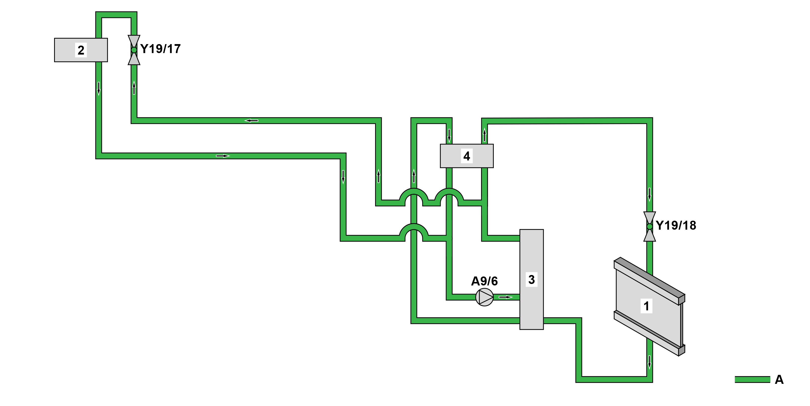
S83.00-A024-79
Refrigerant circuit, schematic diagram |
1 | Evaporator (vehicle interior) | A9/6 | Electric refrigerant compressor | |
2 | Evaporator/heat exchanger | Y19/17 | Expansion valve (vehicle interior) | |
3 | Condenser | Y19/18 | High-voltage battery cooling system evaporator shutoff valve | |
4 | Inner heat exchanger | A | Refrigerant |
Refrigerant circuit, function
The refrigerant circuit generates the cooling that is required for climate control of the vehicle interior by changing the state of the refrigerant from liquid to gaseous. The refrigerant circuit can also be used to reduce the coolant temperature of the coolant circuit for the high-voltage battery.
Detailed information on the cooling of the high-voltage battery is available in the separate function description "High voltage on-board electrical system cooling function".
The refrigerant circuit is regulated by the powertrain control unit. The electric expansion valves are electrically actuated via the automatic air conditioning (AAC) control unit. Requests from the vehicle occupants for regulation of the vehicle interior climate control are also read in by the automatic air conditioning (AAC) control unit.
The refrigerant circuit for climate control of the vehicle interior essentially consists of the following components:
Electric refrigerant compressor (A9/6)
Expansion valve (Y19/17)
High-voltage battery cooling evaporator shutoff valve (Y19/18)
Evaporator (vehicle interior) (1)
Evaporator/heat exchanger (2)
Condenser (3)
Inner heat exchanger (4)
Accumulator (drier)
The individual components of the refrigerant circuit are interconnected through hoses and pipelines and form a closed system.
The refrigerant circuit is split up as follows:
High-pressure side
Low-pressure side
High-pressure side
The electric refrigerant compressor draws in the cold gaseous refrigerant, compresses it, heats it up and the forwards it to the condenser. The compressed hot refrigerant is cooled in the condenser by the outside air flowing past.
The refrigerant changes its state from gaseous to liquid. The refrigerant then flows into the accumulator. The refrigerant is dehumidified when it flows through the fluid reservoir, vapor locks are separated and mechanical impurities are filtered out in order to protect the downstream components. The cleaned refrigerant flows on to the expansion valve and from there the liquid refrigerant which is under high pressure is injected into the evaporator.
Low-pressure side
The liquid refrigerant decompresses in the evaporator and changes its physical state from liquid to gaseous. The evaporation heat required for the evaporation is removed from the blow-by air at the evaporator fins, cooling it down in the process. The refrigerant, which is now completely gaseous, is drawn in again and compressed by the electric refrigerant compressor.
The cooled air is led to the interior of the vehicle by actuating the blower motor (M2).
Climate control regulation
The climate control regulation function encompasses the following subfunctions:
Function sequence for recording and evaluating signals
AC component actuation function sequence
Function sequence for defroster function
Function sequence for evaporator drying process
Heating circuit function sequence
The climate control is performed via the signals recorded by the automatic air conditioning (AAC) control unit (e. g. vehicle interior temperature, outside temperature, coolant temperature, vehicle speed) and depending on the settings selected on the automatic climate control (AAC) control unit.
Function sequence for recording and evaluating signals
The following signals are recorded and evaluated:
Outside temperature
Interior temperature
Temperature and moisture on windshield
Coolant temperature
Evaporator temperature
Refrigerant pressure
Solar radiation
Vehicle speed
Door status
Settings on FRONT heater/air conditioning operating unit switch
Settings on REAR heater/air conditioning operating unit switch
Settings on Audio/COMAND display control unit
Outside temperature
The signal acquisition and actuation module (SAM) control unit (N10/1) reads in the signal from the outside temperature sensor (B14) directly, calculates the outside temperature and sends this to the automatic air conditioning (AAC) control unit. The automatic air conditioning (AAC [KLA]) control unit requires this value to achieve the required interior temperature by adjusting the blend air flaps accordingly.
If the vehicle is stationary, the measured temperature can differ considerably from the outside temperature. The outside temperature is therefore only included in the regulation process when the vehicle speed is 30 km/h for at least 30 s. At speeds lower than 30 km/h and when the ignition is being switched on and off, the last measured temperature value is used.
Interior temperature
The interior temperature is recorded by the interior air temperature sensor of the blower with interior air temperature sensor (M9). The automatic air conditioning (AAC) control unit sends a request to the blower with interior air temperature sensor. The blower is then actuated. The blower sucks in the air for temperature measurement from the vehicle interior. The automatic air conditioning (AAC [KLA]) control unit reads in the interior temperature value directly.
Temperature and moisture on windshield
The temperature and the relative air humidity (dew point temperature) on the inside of the windshield are recorded by the rain/light sensor with additional functions (B38/5).
This sends the "Dew point sensor" signal (humidity sensor) to the signal acquisition and actuation module (SAM) control unit. The signal acquisition and actuation module (SAM) control unit calculates the dew point temperature and sends the signal to the automatic air conditioning (AAC) control unit. The automatic air conditioning (AAC [KLA]) control unit uses the dew point temperature to calculate the relative air humidity and the temperature of the inside of the windshield.
Fogging of the windshield can thus be detected and if the windshield threatens to fog up, corresponding countermeasures are initiated, such as e.g. activation of the electric refrigerant compressor.
Coolant temperature
The temperature of the coolant in the low-temperature circuit 2 is recorded by the coolant temperature sensor 2 (B11/7). The "Coolant temperature sensor" signal is read in directly by the powertrain control unit and evaluated. The powertrain control unit sends the "Coolant temperature" signal to the automatic air conditioning (AAC) control unit. The value is used to regulate the air mixing flaps and to actuate the electric refrigerant compressor.
Evaporator temperature
To prevent the evaporator (1) from icing up, the evaporator temperature is measured by the evaporator temperature sensor (B10/5). The signals of the evaporator temperature sensor are read in directly by the automatic air conditioning (AAC [KLA]) control unit. If the evaporator temperature drops to approx. 2 °C, the electric refrigerant compressor is switched off.
Refrigerant pressure
The refrigerant pressure is recorded by the cooler pressure and temperature sensor (B161/5) and the condenser pressure and temperature sensor (B161/6). The signals of the pressure sensors are read in directly by the automatic air conditioning (AAC) control unit. The pressure is compared with a stored temperature/pressure curve. At a refrigerant pressure of less than 0.8 bar and greater than 30 bar, the electric refrigerant compressor is switched off or not switched in.
At a refrigerant pressure of between 0.8 and 30 bar, the electric refrigerant compressor is switched on or activated again.
Solar radiation
The angle of incidence and the intensity of the solar radiation in the vehicle are recorded by the sun sensor in the rain and light sensor with additional functions (B38/5). The signal acquisition and actuation module (SAM) control unit reads in the "sun sensor" signal, evaluates it and sends the "Solar radiation" signal to the automatic air conditioning (AAC) control unit. In the event of one-sided solar radiation, an appropriate temperature difference is set between the left and the right specified control temperatures.
Vehicle speed
The vehicle speed is sent by the Electronic Stability Program (ESP) control unit (N30/4) to the automatic air conditioning (AAC) control unit. The vehicle speed is used by the regulation for internal calculation of the outside temperature, e.g. during operation while at a standstill.
Door status
The status of the respective door is determined by the following control units:
Left front door control unit (N69/3)
Right front door control unit (N69/4)
The respective control unit then sends the "Door rotary tumbler switch" status to the automatic air conditioning (AAC) control unit. If the door is open, the automatic air conditioning (AAC) control unit retains the current blower setting in order to avoid unnecessary readjustment in the event of large temperature differences between the interior air and outside air.
Settings on FRONT heater/air conditioning operating unit switch
The climate control settings for the driver and front passenger areas can be adjusted using the following buttons on the FRONT heater/air conditioning operating unit switch (S98/1):
Left temperature selection button (S98/1s1)
Air distribution button (S98/1s2)
Blower setting button (S98/1s3)
"AUTO" button (S98/1s4) (with code HH4 (THERMOTRONIC automatic air conditioning))
Defrosting button (S98/1s5)
Climate control "MENU" and residual heat "REST" button (S98/1s6)
Rear window heater button (S98/1s7)
A/C button (S98/1s8)
Air recirculation mode button (S98/1s9)
Right temperature selection button (S98/1s11)
Stationary heater button (S98/1s12)
The settings are sent by the FRONT heater/air conditioning operating unit switch (S98/1) to the automatic air conditioning (AAC) control unit where they are processed. This data is used to regulate the air flow, air distribution and temperature. The selected settings are shown on the Audio/COMAND display control unit (A40/8).
Settings on REAR heater/air conditioning operating unit switch
Vehicles with code HZ7 (TEMPMATIC semi-automatically controlled air conditioning, in rear)
The settings for the rear compartment climate control can be set using the following buttons on the REAR heater/air conditioning operating unit switch (S98/2):
REAR temperature selection button (S98/2s1)
REAR blower button (S98/2s2)
The settings are sent by the REAR heating/air conditioning operating unit switch (S98/2) to the automatic air conditioning (AAC) control unit. The data is used to regulate the air volume and temperature for the rear compartment, depending on the front compartment.
Settings on Audio/COMAND display
The menu of the Audio/COMAND display control unit (A40/8) can be used to switch off the air conditioning system or to select the climate control functions. The control signals are sent by the Audio/COMAND display control unit via the head unit (A26/17) to the automatic air conditioning (AAC) control unit.
AC component actuation function sequence
The function sequence for actuating the A/C components encompasses the following subfunctions:
Actuation of the blower motor
Actuation of the air duct flaps
Actuation of electric refrigerant compressor
Actuation of high voltage PTC heater control unit
Actuation of electric additional water pump
Actuation of the blower motor
Ventilation is achieved using the blower motor (M2). The automatic air conditioning (AAC) control unit forwards the request to the blower motor (M2).
The blower motor is switched off in the event of an accident.
Actuation of the air duct flaps
The air distribution in the vehicle interior is controlled by adjusting the air ducting flaps in the air conditioner housing.
Actuation of electric refrigerant compressor
The electric refrigerant compressor is responsible for drawing in the refrigerant and compressing it.
The automatic air conditioning (AAC) control unit actuates the electric refrigerant compressor.
The electric refrigerant compressor is switched off via the interlock circuit in the event of an accident.
Actuation of high voltage PTC heater control unit
The high voltage PTC heater control unit (N33/7) is switched in as required by the automatic air conditioning (AAC) control unit.
The high voltage PTC heater control unit is switched off in the event of an accident.
Actuation of electric additional water pump
The heated coolant passes through the heater heat exchanger, which dissipates heat to the air blowing by.
The electric additional water pump (M13/15) is also actuated to ensure that the flow volume required to heat up the blowby air is achieved. The electric additional water pump is actuated by the automatic air conditioning (AAC) control unit.
Function sequence for defroster function
When the defroster button (S98/1s5) is pressed, all air flaps are closed with the exception of the defroster flaps and the fresh/recirculated air flap. These are fully opened. The defroster flaps are adjusted so that the maximum air flow is directed to the windshield and the front side windows. The blend air flaps are set to full warm air supply.
The automatic air conditioning (AAC) control unit actuates the blower motor (M2) so that optimum defrost mode is guaranteed depending on the outflowing air temperature.
The electric refrigerant compressor is switched-in to ensure that the vent air is dried. The air is dried and then heated up to the maximum temperature.
Additional function requirements for evaporator drying
Air conditioning system was active at least once during the last activation cycle.
Outside temperature > 20 °C
Doors closed
Kilometer reading > 250 km
Function sequence for evaporator drying process
To counteract evaporator odors in the vehicle interior and fogging of windows when starting the air conditioning or climate control, an evaporator drying process is performed.
After switching off the electric vehicle, a timer is activated in the instrument cluster (IC) control unit(A1/1). The "Electric drive READY" status is sent by the powertrain control unit to the instrument cluster (IC) control unit.
After a waiting time of one hour, the instrument cluster (IC) control unit sends the request for evaporator drying to the automatic air conditioning (AAC) control unit, which then starts the evaporator drying process. To do this, the blower motor is actuated for 30 minutes at the lowest stage.
The automatic air conditioning (AAC) control unit sends the request to the blower motor. This then starts running at the lowest speed. The air supply serves to reduce residual moisture in the evaporator.
Heating circuit function sequence
Driven by the electric additional water pump, the coolant circulates in the heating circuit. Here, it absorbs the heat from the high-voltage PTC heater control unit or from the high-voltage battery, depending on the given operating condition.
The heated coolant is directed e.g. through the heater core, which dissipates the heat to the air blowing by.
The condensation prevention switchover valve (Y16/10) regulates the flow of coolant to the heater core or to the low-temperature circuit 2 (coolant circuit of high-voltage battery) and the heater core.
Electrical function schematic for air conditioning | With CODE HH9 (TEMPMATIC semi-automatically controlled air conditioning) | ||
Electrical function diagram for automatic air conditioning (AAC [KLA]) | With code HH4 (THERMOTRONIC automatic air conditioning) | ||
Electric vehicle auxiliary climate control, function | |||
High voltage PTC heater, function | |||
Overview of system components of climate control, electric vehicle |