

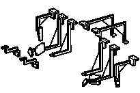

209 589 00 23 00
Welding devices
Check and welding device
Check and welding device
Side portal frame
203 589 00 23 00
209 589 05 23 00
210 589 17 23 00


129 589 03 23 00
Portal frame
Multi-Z elements MZ 260
140 589 26 23 00
Repair materials
Number | Designation | Order number |
BR00.45-Z-1003-01A | Sealant, white, 310 ml, DB supply specification 6069.20 | A 001 989 63 20 |
BR00.45-Z-1041-01A | Seam sealant, sprayable 310 ml | A 002 989 84 20 |
BR00.45-Z-1003-05A | Cavity preservation, solvent-free (1 l container) | A 000 986 72 70 05 |
BR00.45-Z-1001-07A | Zinc dust paint suitable for spot welding | A 000 986 34 42 |
BR00.45-Z-1002-13A | Polygrip countersunk head rivet, 6.414 | A 003 990 86 97 05 |
BR00.45-Z-1001-13A | Blind rivet 6.414 | A 003 990 35 97 |

P63.20-3868-08
1 Install inner and outer A-pillar with side portal frame, front portal frame, check and welding device and clamping pliers, fit and fasten.
2 Drill dia. 6.5 mm rivet holes (areas K and L1).
3 Remove outer A-pillar
4 Deburr rivet holes on both sides

P63.20-3874-09
5 Set inner A-pillar with threaded clamping grippers and clamping pliers.
6 Drill dia. 6.5 mm rivet holes (areas F, G, I1, I2 and L1).
7 Remove Inner A-pillar and deburr rivet holes on both sides.
8 Install Inner A-pillar with welding devices, clamping pliers and screw-on clamping gripper, fit and fasten.
9 Weld in inner A-pillar with (areas C, D1, E, F1, H, J, K and L).
10 Weld in with (areas D, E1 and I).
11 Rivet inner A-pillar with 6.4 x 14 dia. Polygrip flat head rivets (areas F, G, I1 and L1).
12 Countersink inner A-pillar rivet hole (area I2).
13 Rivet Inner A-pillar with 6.4 x 14 Polygrip countersunk rivet (area I2).

P63.20-3877-08
14 Grind connection surfaces down to bare metal in shaded areas. Sand spot weld flanges to bare metal on both sides
15 Remove grinding and drilling chips using wet/dry vacuum cleaner.
16 Coat insides of spot welding flanges and rivet connections with zinc dust paint.

P63.20-3880-08
17 Weld in reinforcement on inner A-pillar with
(area A).
18 Weld in reinforcement on inner A-pillar with
(area B).
19 Rivet reinforcement on inner A-pillar with 6.4 x 14 dia. Polygrip flat head rivets (area A).
20 Weld in reinforcement on inner A-pillar with (area V).