The next steps are shown on the component part in the event of damage to the left side of the vehicle and must be performed in the same way for vehicles with damage on the right side of the vehicle.
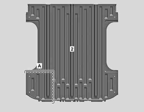
1 | Mark separating point on vehicle floor (2) (area A). |
Use dimension for separating cut from the vehicle. |
2 | Cut vehicle floor (2) at separating point (area A). |
Commercially available devices/tools |
3 | Dispose of the larger remaining part of the vehicle floor (2). |
Shown on model 907.6 except code IR2 (wheelbase 3,250 mm) |
D61.10-A024-11

4 | Drill holes in the vehicle floor section (1) with a diameter of 7 mm (area C). |
Commercially available devices/tools |
Model 907.6/7 |
Model 907.6/7 |
5 | Grind mating surfaces on the vehicle floor section (1) down to bare metal in the cross-hatched areas and around the holes (area C). |
Commercially available devices/tools |
Model 907.6/7 |
Model 907.6/7 |
6 | Remove shavings and drill chips. |
Commercially available devices/tools |
7 | Zinc dust paint to insides of spot weld flanges. |
D61.10-A026-03

8 | Grind mating surface down to bare metal in the cross-hatched area on the vehicle floor section (1). |
Commercially available devices/tools |
9 | Remove shavings. |
Commercially available devices/tools |
D61.10-A025-01
Powiązane dokumenty
- as0000z001701a Niebezpieczeństwo obrażeńo elementy pojazdu o ostrych krawędziach.