
Puller
000 589 45 33 00

P26.50-2199-05
1 Position and clamp puller (3) at cutout (arrow) on the 5th gear wheel (2).
2 Position output shaft (1) using puller (3), as shown, into the hydraulic press (4).
Hydraulic press (4) 25 t
http://gotis.aftersales.mercedes-benz.com
3 Use heat gun to heat up 5th gear wheel (2) and press down using the hydraulic press (4).
Heat gun
http://gotis.aftersales.mercedes-benz.com
Hold output shaft (1) firmly during the pressing-out procedure, to prevent if falling and being damaged.
4 Remove puller (3) from 5th gear wheel (2).

P26.50-2200-05
5 Remove idler gear for 4th. gear (5) from output shaft (1).
6 Remove cone ring (6) and synchronizer ring (8) from output shaft (1).
7 Remove needle roller bearing (9) from output shaft (1).
8 Detach and remove sliding sleeve (7) upwards from synchronizer body (10).
Observe installation position of sliding sleeve (7). Make sure that the thrust pieces (11) do not drop out and fall down.
9 Remove thrust pieces (11) from the synchronizer body (10).
P26.50-2201-05
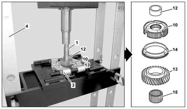
10 Position and clamp puller (3) below the idler gear for the 3rd. gear (13).
11 Position output shaft (1) using puller (3), as shown, into the hydraulic press (4).
12 Use heat gun to heat up sleeve (12) and synchronizer body (10) and press down using the hydraulic press (4).
Hold output shaft (1) firmly during the removal procedure, to ensure that it does not fall down and suffer damage.
13 Remove sleeve (12), synchronizer body (10), synchronizer ring (14) and idler gear for 3rd. gear (13) from output shaft (1).
14 Remove puller (3) from output shaft (1).
15 Remove needle bearing (15) from output shaft (1).

P26.50-2202-05
16 Use a suitable screwdriver to detach and remove circlip (16) from clamping jaws (18).
17 Detach and remove clamping jaws (18) from output shaft (1).
18 Remove idler gear for 2nd. gear (17) from output shaft (1).
19 Remove needle bearing (19) from output shaft (1).

P26.50-2203-08
20 Detach snap ring (20) using a suitable pair of pliers and remove from output shaft (1).
21 Remove synchronizer ring (21) from output shaft (1).
22 Detach sliding sleeve (22) carefully from synchronizer body (23) and remove the balls (25), thrust pieces (26) and the springs (24).
Observe installation position of sliding sleeve (22). Makes sure that the balls (25), thrust pieces (26) and springs (24) do not drop down.
23 Insert output shaft (1) as shown with idler gear for 1st. gear (28) into hydraulic press (4).
24 Remove synchronizer body (23), synchronizer ring (27) and idler gear for 1st. gear (28) using the hydraulic press (4) from the output shaft (1).
Hold output shaft (1) firmly during the removal procedure, to ensure that it does not fall down and suffer damage.
25 Remove needle bearing, which is located under idler gear for the 1st. gear (28), from the output shaft (1).