
3 | Intake camshaft |
D05.20-1120-06
| Remove | ||
1 | Remove cylinder head cover | ||
2 | Position piston of cylinder 1 to ignition TDC | ||
Retaining pins | |||
Socket wrench bit | |||
| Check | ||
3 | Check basic position | The markings on the camshaft sprockets must be positioned opposite each other (arrows C). The markings on the intake camshaft (3) and exhaust camshaft must be aligned (arrows D). | |
If the markings (arrows C) are not opposite each other or are not in line with markings on the camshaft bearing caps (arrows D) then the intake camshaft (3) and exhaust camshaft must be removed and installed turned through the appropriate amount. | |||
| |||
Remove/install camshafts | |||
| Install | ||
4 | Install cylinder head cover |
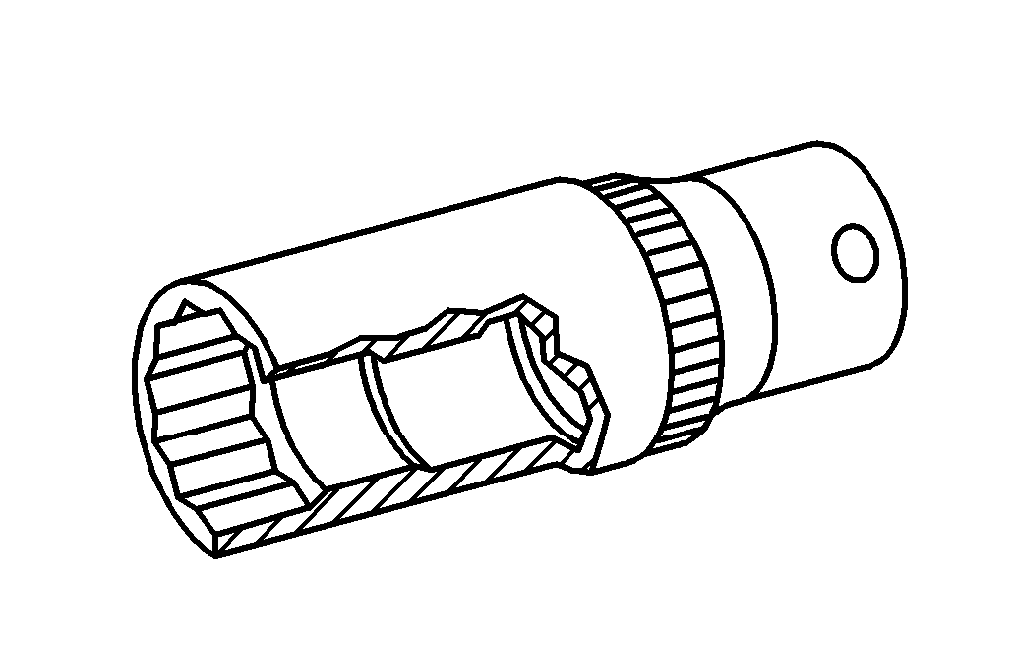

001 589 65 09 00
Socket wrench bit
111 589 03 15 00
Retaining pins