

602 589 04 63 00
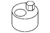
Thrust spindle
602 589 04 63 01
Pressure pins
651 589 00 40 00
Counterholder
651 589 08 40 00
Counterholder


651 589 03 40 00
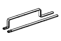
Hold-down device
602 589 02 33 00
Chain separating tool
602 589 00 98 00
Case

The timing case shaft must be covered with clean rag to protect against falling parts before doing work on the timing chain (1). Parts which have nevertheless managed to fall into the timing case recess must be removed.
Engine damage may occur otherwise.
1 | Prepare separate parts of the special tools. |
The separate parts of the special tools are stored in the case. |
D05.10-1184-01


D05.10-1185-01
D05.10-1201-01
2 | Insert pressure pin (3) in thrust spindle (2) and tighten union nut (4). |
3 | Screw thrust spindle (2) into pilot bushing (5). |
The pressure pin (3) must not project into beveled tapered area of pilot bushing (5). |
4 | Screw pilot bushing (5) into chain breaker tool (6). |
5 | Attach hold-down tool (7), as shown, and tighten down screw/bolts (8). |

6 | Fit chain breaker tool (6) onto timing chain (1). |
When putting the pilot bushing (5) in place, ensure that this encloses the pin for the timing chain link pin. |
Slowly turn engine using counterholder at the crankshaft in direction of engine rotation if necessary until perfect placing is possible. |
D05.10-1202-11
7 | Screw in thrust spindle (2) and separate timing chain (1). |
8 | Remove thrust spindle (2) and remove chain breaker tool (6) with pressed out pin. |