ar0120d5018tsv

Remove/install cover of left cylinder head cover

Typ ar · temat 01.20 · wersja 0100 · 2018-06-08

Dotyczy: Engine 642 in model 907

Niedostępne w języku „pl”; wyświetlono w języku Angielski.

Umiejscowienie

Grupa funkcyjna 1 Silnik › 01 Silnik kompletny, odpowietrzenie silnika, głowica cylindrów, skrzynia korbowa › 01.20 Odpowietrzanie silnika, pokrywa głowicy cylindrów — Seria 907

EinPAS 15 Silnik › 15.15 Silnik spalinowy kompletny/obudowa silnika/mechanizm korbowy › 15.15.45 Osłona/okładzina — Seria 907

Dotyczy też silników/skrzyń biegów: 642 ***

AR01.20-D-5018TSV

Remove/install cover of left cylinder head cover

22.05.2018

Engine

642 in model 907

Remove/install cover of left cylinder head cover

D01.20-1058-09

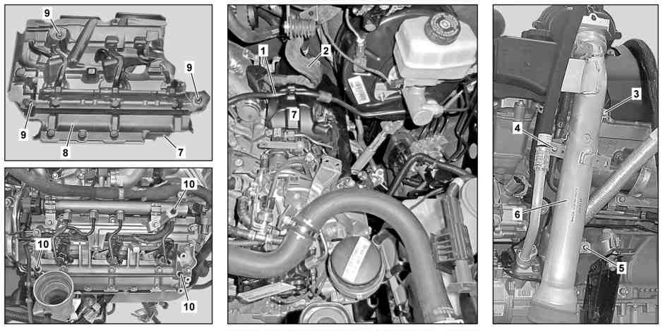
Shown with CODE HH9 (Semi-automatically regulated air conditioning, TEMPMATIC)

1

Vacuum line

5

Screw

9

Support

2

Electrical wiring harness

6

Charge air line

10

Ball head

3

Screw

7

Cover

4

Screw

8

Insulation

Remove/install

1

Remove the washer fluid reservoir for the windshield washer system and place it out of the working area.

AR82.35-D-6000TSR

Do not remove the lamp unit. Do not remove any connected lines.

2

Remove engine cover.

AR01.10-D-2405TSV

3

Remove the noise damper for the exhaust gas turbocharger.

AR09.40-D-6920TSV

4

Remove the vacuum line (1) from the cover (7).

5

Remove the electrical wiring harness (2) from the cover (7).

6

Remove bolts (3, 4).

Bolt, charge air line upstream of charge air cooler to bracket

*BA09.41-N-1005-01O

Bolt, charge air line upstream of charge air cooler to cylinder head cover

*BA09.41-N-1004-01O

Set of flexible head wrenches

*001589810900

7

Loosen the bolt (5) a few turns.

The charge air line (6) must be removed.

Bolt, charge air line upstream of charge air cooler to engine carrier

*BA09.41-N-1006-01O

Set of flexible head wrenches

*001589810900

8

Press the charge air line (6) to the side.


Carefully press the charge air line (6) to the side.
This prevents damage to surrounding assembly parts.

9

Unclip the cover (7) together with the insulation (8) and remove upward.

Installation: Position the insulation (8) in the cover (7) correctly. Engage the mounts (9) for the cover (7) on ball heads (10).

10

Install in the reverse order

Charge air pipe, charge air cooling, mixer housing

Number

Designation

Engine 642

BA09.41-N-1004-01O

Bolt, charge air line upstream of charge air cooler to cylinder head cover

Nm

9

Charge air pipe, charge air cooling, mixer housing

Number

Designation

Engine 642

BA09.41-N-1005-01O

Bolt, charge air line upstream of charge air cooler to bracket

Nm

9

Charge air pipe, charge air cooling, mixer housing

Number

Designation

Engine 642

BA09.41-N-1006-01O

Bolt, charge air line upstream of charge air cooler to engine carrier

Nm

9

Remove/install cover of left cylinder head cover

001 589 81 09 00

Set of flexible head wrenches

Powiązane dokumenty