AR33.20-P-0440B | Replace supporting joint | 12.11.09 |
MODEL 170
MODEL 202
MODEL 208
MODEL 210 (except 210.08 /28)

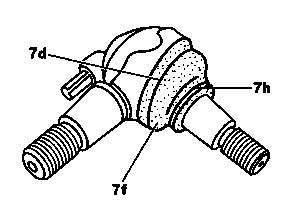
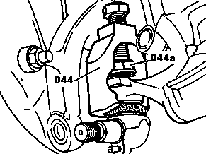
P33.20-0260-01
P33.20-0218-01
P33.20-0216-01
Modification notes
| Remove/install | ||
| To remove and install the supporting joint the shock absorber must be installed. | ||
1 | Remove front wheel | ||
2 | Unscrew nuts from supporting joint | Install new self-locking nut. | |
3 | Screw thrust piece (044a) onto the respective ball stud of the supporting joint | | |
4 | Press out supporting joint using puller (044) from steering knuckle or transverse control arm | Clean conical joint. | |
5 | Check supporting joint | Replace if necessary | |
Installation: After installing new supporting joint, apply an approved EP filler to protect it against corrosion. | |||
| Supporting joint with integrated rebound stop | Model 202 | |
6 | Install in the reverse order |
Wheel location, hub
Number | Designation | Model | Model | Model | ||
BA33.20-P-1006-01A | Self-locking nut, supporting joint to lower transverse control arm | Nm | 105 | 105 | 105 | |
Wheel location, hub
Number | Designation | Model | ||
BA33.20-P-1006-01A | Self-locking nut, supporting joint to lower transverse control arm | Nm | 105 | |


140 589 00 63 00
202 589 02 33 00
Puller
Thrust piece
참조 문서
- ap4010p4050z 휠 탈, 장착 및 필요시 교체
- ar3320p0425a
- bt3320p000201a