91-125 Removing and installing gear for backrest adjustment
Front seat removed (91-100) Side covering on backrest frame removed (91-60) Covering on rear of front seat backrest removed (91-065) | Operation no. of operation texts and work units standard texts and flat rates
|

P91-0078-57x
Gear on inside of seat | |
Flexible drive shaft (1) | remove. |
Motor (2) | unscrew (4 screws). |
Toothed belt (3) | remove. |
Motor (2) on driver's backrest | screw on hand-tight. |
Clamping pin (4) on backrest lock | knock out, 3 mm diameter, while holding with setting iron or hammer. |
Screws (5) | 2 each (12 mm Allen screws) unscrew. |
Gear spindle (6) on backrest lock | unscrew. |
Gear (7) | remove. |
Gear spindle (6) | screw into backrest lock until clamping pin (4) can still just be knocked in. |
Screws (5) | 2 each (12 mm Allen screws), screw in. |
Clamping pin (4) | install. Total length 30 mm. |
Adjust backrest lock | see gear, outside of seat. |
Continue to reinstall | in opposite order. |
Gear on outside of seat
P91-0078-57x
Flexible drive shaft (1) | remove. |
Clamping pin (8) on backrest lock | knock out, 3 mm diameter, while holding with setting iron or hammer. |
Screws (9) | 2 each, 12 mm Allen screws, unscrew. |
Stop cable | fold away downward. |
Gear spindle (10) on backrest lock | unscrew. |
Gear (11) | remove. |
Gear spindle (10) | screw into backrest lock until clamping pin (8) can just be knocked in. |
Screws (9) | 2 each (12 mm Allen screws), screw in while simultaneously inserting the stop cable eye. |
Stop cable eye | do not pinch when tightening screws (9). |
Clamping pin (8) | install, total length 37 mm. |
Both gear spindles (6 and 10) | screw all the way up against the stop. |
Backrest lock | check, both locks must catch simultaneously and completely. |
Adjust backrest lock | by turning gear drive shaft slightly to correct. |
The control cables on the backrest lock | must be adjusted to play of 0 - 1 mm. |
Flexible drive shaft (1) | install and fasten with mount on backrest frame. |
Check backrest lock | with both microswitches (Diagnosis Manual). |
Continue to reinstall | in opposite order. |
Installation note
The clamping pins in the backrest locks have different lengths and are therefore not interchangeable.
Backrest lock - inside of seat
Clamping pin length 30 mm
Dia. 3 mm
Backrest lock - outside of seat
Clamping pin length 37 mm
Dia. 3 mm
The gear screws (5 and 9) on the left and right gears have different screw head lengths and are therefore not interchangeable.
The screw with the screw head length of 12 mm is for the gear on the inside of the seat.
The screw with the screw head length of 18 mm is for the gear on the outside of the seat.
The threads on the gear screws (5 and 9) are micro-encapsulated and must be replaced after disassembly or coated with screw securing agent.
Tightening torque: 35 Nm.
Removal, installation
-------------------------------
Gear on inside of seat

1 Unscrew mount on backrest frame and pull flexible drive shafts on left and right out of gear drive shafts.
P91-2093-13x
2 Unscrew screws and remove toothed belt from motor.
3 Screw motor back onto driver's backrest and tighten hand-tight.
4 Unlock backrest and tilt forward.
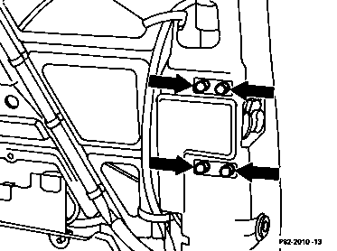
P82-2010-13x

5 Knock out clamping pin, diameter 3 mm, while holding with setting iron or hammer (arrow).
P91-2090-13x

6 Unscrew screw on outside (arrow).
P91-2091-13x

7 Unscrew screw on inside (arrow).
P91-2092-13x

8 Screw gear spindle out of backrest lock manually.
9 Remove gear.
P91-2103-13x

10 Check plastic bushings, replace if damaged (arrows).
P91-2103-13/Ax

11 Screw gear spindle into backrest lock so that the clamping pin can still just be knocked in.
P91-2103-13/Bx
12 Screw in inner and outer screws. Observe installation note.
Tightening torque: 35 Nm.
P91-2092-13x

13 Install clamping pin.
Length of clamping pin: 30 mm.
P91-2122-13x

14 Turn left and right gear spindle all the way up against the stop. To do this stick flexible drive shaft onto gear drive shaft and turn manually.
P91-2118-13x

15 Check backrest lock; both locks should catch simultaneously and completely.
P91-2089-13x

16 The backrest lock adjustment can be corrected by turning the gear drive shaft slightly.
P91-2115-13x

17 In the locked state the control cables for the backrest lock should have play of 0 - 1 mm.
P91-2077-13x

18 Install toothed belt and tension. Adjust toothed belt tension to play of 3 - 7 mm at a manual force of approx. 30 N.
P91-5206-13

19 Install flexible drive shaft without changing adjustment made previously on gear drive shafts.
P91-2059-13Ax
20 Lock backrest locks and ensure that they are completely locked by electrically checking the microswitches on the left and right (see Diagnosis Manual, Body, Volume 1, Section 4.1, Model R 129).
21 Continue to reinstall in opposite order.
P91-2093-13x
Gear on outside of seat
22 Remove flexible drive shaft (arrow).

23 Knock out clamping pin, 3 mm diameter, on backrest lock while holding with setting iron or hammer (arrows).
P91-2096-13x

24 Unscrew screw on outside (arrow).
P91-2097-13x

25 Unscrew screw on inside (arrow).
P91-2099-13x

26 Pull stop cable down and out (arrow)
27 To improve access to the gear spindle disconnect pull cable for backrest release on backrest lock.
P91-2100-13x

28 Unscrew gear spindle manually on backrest lock (arrow).
29 Remove gear.
P91-2098-13x

30 Before installing gear check plastic bushings, replace if damaged. Install both bushings with the collar pointing inward.
Plastic bushing on inside
P91-2101-13x

Plastic bushing on outside
P91-2102-13x
31 Insert gear into backrest strut and turn gear spindle into backrest lock until the clamping pin can still just be knocked in (arrow).
32 Hook in and clip on control cable for backrest release.
P91-2098-13x
33 Screw in screws on outside and inside while inserting stop cable; do not pinch cable eye.
Observe installation note.
Tightening torque: 35 Nm.
P91-2097-13x
34 Install clamping pin.
Length of clamping pin: 37 mm.
P91-2096-13x
35 Turn left and right gear spindle all the way up against the stop. For this purpose stick flexible drive shaft onto gear drive shaft and turn manually.
P91-2115-13x
36 Check backrest lock; both locks should catch simultaneously and completely.
P91-2089-13x
37 The backrest lock adjustment can be corrected by turning the gear drive shaft slightly.
P91-2115-13x
38 The pull cables for releasing the backrest must be adjusted to a play of 0 - 1 mm in the locked state.
P91-2077-13x
39 Install flexible drive shaft and screw onto backrest frame with mount without turning the previously adjusted gear shafts.
P91-2093-13x
40 Lock backrest lock and ensure that they are completely locked by electrically checking the microswitches on the left and right (see Diagnosis Manual, Body, Volume 1, Section 4.1, Model R 129).
Note
When the front seat backrest is completely locked a play of 15 - 20 mm is permissible at the top of the backrest.
41 Continue to reinstall in opposite order.
P91-2059-13/Ax