83-5982 Testing, removal and installation of thermal fuse and temperature sensor
DBW 2012 heater unit |
Switching points
Temperature sensor: Cut-out temperature Cut-in temperature | 78°C 63°C |
Caution:
There is a risk of injury due to hot coolant escaping when changing the thermal fuse and the temperature sensor.
Note
Before changing the thermal fuse and the temperature sensor, reduce pressure by opening the radiator cap. If necessary, pinch off the coolant hoses on the heater unit.

Testing, removal and installation
-------------------------------
Temperature sensor
1 Press clip (arrow) downwards and disconnect plug connection.
2 Remove temperature sensor (1) with sealing ring (2).
Installation note
Replace sealing ring (2).

3 Immerse temperature sensor (1) at 20°C and 100°C water temperature and measure resistance (W) in accordance with the diagram.
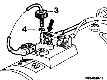
Thermal fuse
4 Press clip (arrow) downwards and disconnect plug connection.
5 Test thermal fuse (3) for continuity.
6 Remove thermal fuse (3) with O-ring (4).
Installation note
Replace O-ring (4).
7 Install parts in reverse sequence.