ra4206abs0845x

0845 - Removal and installation of the hydraulic unit ABS T2 model 667, 668, 669, 670

Tipo ra · tema 42.30 · versione 9203 · 1992-01-15

Valido per:

Non disponibile in “it”; mostrato in Inglese.

Collocazione

Gruppo funzionale 2 Telaio › 42 Freni impianto idraulico e meccanico › 42.30 Sistema antibloccaggio ruote (ABS) — Serie 667 (modelli 0**, 30*, 34*, 36*) · Serie 668 (modelli 0**) · Serie 669 · Serie 670 (modelli 0**, 1**, 30*, 31*, 34*, 36*, 41*, 46*)

42 - 0845 Removal and installation of hydraulic unit

Tightening torque Nm

Retaining screw of brake line to

hydraulic unit

14

0845 - Removal and installation of the hydraulic unit ABS                       
	T2 model 667, 668, 669, 670
0845 - Removal and installation of the hydraulic unit ABS                       
	T2 model 667, 668, 669, 670

Special tools

0845 - Removal and installation of the hydraulic unit ABS                       
	T2 model 667, 668, 669, 670

Removal

1 With the ignition switched off, disconnect ground cable at the battery.

2 Detach brake lines on the hydraulic unit. Seal connections and lines with blind plugs.

Caution

The hexagon socket bolts on the hydraulic unit must not be slackened.

0845 - Removal and installation of the hydraulic unit ABS                       
	T2 model 667, 668, 669, 670

3 Unscrew fixing screw for cover. Remove cover.

0845 - Removal and installation of the hydraulic unit ABS                       
	T2 model 667, 668, 669, 670

4 Unlock locking device for multiple plug and detach plug.

0845 - Removal and installation of the hydraulic unit ABS                       
	T2 model 667, 668, 669, 670

5 Disconnect additional ground cable.
0845 - Removal and installation of the hydraulic unit ABS                       
	T2 model 667, 668, 669, 670

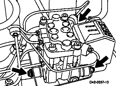
6 Unscrew hexagon nut and remove hydraulic unit from bracket.

7 Check damping rubbers for wear or damage and replace if required.

Only store hydraulic unit upright.

0845 - Removal and installation of the hydraulic unit ABS                       
	T2 model 667, 668, 669, 670

Installation

1 Install hydraulic unit in bracket and fasten with hexagon nuts.

0845 - Removal and installation of the hydraulic unit ABS                       
	T2 model 667, 668, 669, 670

2 Connect additional ground strap.

0845 - Removal and installation of the hydraulic unit ABS                       
	T2 model 667, 668, 669, 670

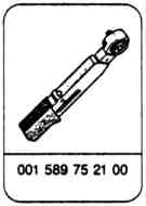
3 Connect brake lines to hydraulic unit and tighten using . (14 Nm)

Caution

Do not confuse brake lines.

001 589 75 21 00

000 589 75 03 00

0845 - Removal and installation of the hydraulic unit ABS                       
	T2 model 667, 668, 669, 670

Vehicle with diagonal brake circuit split

Model designation 667

1.1 = from brake master cylinder, intermediate piston circuit

1.2 = from brake master cylinder, plunger circuit

2.1 = to left-hand front wheel brake

2.2 = to right-hand front wheel brake

2.3 = to right-hand rear wheel brake

2.4 = to left-hand rear wheel brake

Vehicle with TT brake circuit split

Model designation 667 (with optional equipment code A50); 668 - 670

1.1 = from brake master cylinder, intermediate piston circuit

1.2 = from brake master cylinder, plunger circuit

2.1 = to left-hand front wheel brake

2.2 = to left-hand rear wheel brake

2.3 = to right-hand front wheel brake

2.4 = to right-hand rear wheel brake

0845 - Removal and installation of the hydraulic unit ABS                       
	T2 model 667, 668, 669, 670

4 Fit multiple connector. Engage locking device.

0845 - Removal and installation of the hydraulic unit ABS                       
	T2 model 667, 668, 669, 670

5 Fasten cover to hydraulic unit using the screw.

6 Bleed brake system and check for leaks.

(42 - 0016)

7 Connect ground cable to the battery.

8 Perform test program. (Refer to Diagnosis Manual - Transporter T1/T2 volume 1)

Documenti citati