27-640 Dismantling and assembling transmission
Operation number of the operation texts and work units or standard texts and flat rates: 27-4010 |

P27-2006-13
Dismantling
1 Remove control pressure cable. Release locking device using a screwdriver (arrow) and detach control pressure cable.
P27-2005-13
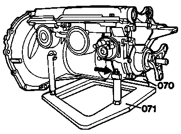
2 Bolt mounting frame to assembly jig. Position transmission in the mounting frame and secure in place with the bolt (arrow).
070 Assembly jig 116 589 06 59 00
071 Mounting frame 126 589 10 63 00
P27-2004-13
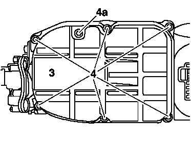
3 Unscrew bolts with washers (4) and remove
oil pan (3).
Installation note
Tightening torque 8 Nm.
P27-2003-13
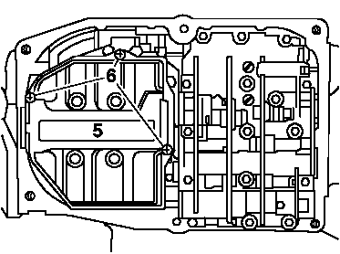
4 Unscrew cross-head bolts (6) and remove oil
filter (5).
Installation note
Tightening torque 4 Nm.
P27-2002-13
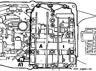
5 Unscrew bolts (7/7a) and remove shift valve
body (A).
Installation note
Tightening torque 8 Nm.
Note different lengths of bolts.

P27-2001-13
6 Unscrew hexagon bolts (140). Remove bracket (141) with leaf spring (142).
Installation note
Tightening torque 8 Nm.
7 Unscrew bolts with washers and lift off lower cover (13) with intermediate plate (14) and oil pipe (9). Dismantle lower cover (27-435).
Installation note
Tightening torque 8 Nm.

P27-2082-13
8 Remove one-way valve (49), brake band guide B2 (101), locating pin (135), temperature throttle (117) and oil deflector (119). Check that filler element (128) is correctly seated.
Note
As of 08/90, the filler element (128) is no longer featured in several models of transmission.

P27-2081-13
9 Push in brake band plunger cover B2 (17) and remove circlip (23).
10 Remove brake band plunger cover.

P27-2083-13
11 Pull out brake band plunger B2 (15) with thrust pin (26) clipped in.
Installation note
Adjust clearance "L" to 5.5 - 5.7 mm with thrust pin (26) (item 127).

P27-2080-13
12 Apply assembly device, bolt onto transmission housing and clamp.
13 Remove circlip (41).
026 Assembly device 201 589 03 59 00

P27-2079-13
14 Release assembly device (026) and take off brake band plunger B1 (37) with thrust pin, cover (40) and return springs (35, 36).
15 Unscrew assembly device (026).
Installation note
Adjust clearance "L" to 1.8 - 2.0 mm as described in items 118 to 124.

P27-2078-13
16 Pull out brake band guide B1 (34).

P27-0023-13
17 Unscrew screw plug (33) for thrust element B1 or pressure switch for transmisison overload protection (33b).
Installation note
Tightening torque 70 Nm. Replace O-Rings.
18 Take out thrust element B1 (31)

P27-2084-13
19 Unscrew hexagon bolt (51) and pull off range selector lever (52).
Installation note
Tightening torque 8 Nm.

P27-2093-13
20 Unscrew hexagon bolts (55) and remove starter lockout switch (53).
Installation note
Tightening torque 8 Nm.

P27-0017-13
21 Remove vacuum unit (60) after unscrewing hexagon socket bolts (58) with retaining plate (57).
Installation note
Tightening torque 8 Nm.
22 Remove heat expansion pin (59a) and modulating pressure regulator valve (59).

P27-2092-13
23 Unscrew kickdown solenoid valve (61).
Installation note
Tightening torque 20 Nm.
24 Enguage parking lock. Unscrew twelve-point collared nut (62) and pull off propeller flange or internal gear (64a).
Socket wrench 126 589 02 09 00.
Installation note
Tightening torque 120 Nm.

P27-2091-13
25 Remove washer (65).
26 Unscrew hexagon bolts (71).
27 Loosen rear cover (70) by tapping gently with a plastic mallet and remove.
28 Dismantle rear cover (27-450).

P27-2033-13
29 In vehicles with electronic speedometer, remove parking lock gear (73) with rotor, parking lock pawl (74) and expanding spring (75).

P27-2090-13
30 In vehicles with mechanical speedometer, remove oil pipe (102), parking lock gear (73) with helical gear, parking lock pawl (74) and expansion spring (75).

P27-2088-13
31 Pull off plastic guide (80) upwards and then remove roller (81).

P27-2064-13
32 Unscrew hexagon socket bolt (82a), pull out shaft (76) and remove notched plate (82) with spring linkage.

P27-2087-13A
33 Unscrew hexagon socket bolt (84a) and remove with oil pipe (84)
Installation note
Tightening torque 8 Nm.
Note
As from 04/89 the oil pipe (84) for governor lubrication is not used any more.

P27-2102-13
34 Unscrew nut (44) from axial retainer for the centrifugal governor.
Installation note
Tightening torque 6 Nm.
35 Unscrew hexagon socket bolts (45) and remove secondary pump (20).
Installation note
Tightening torque 8 Nm.

P27-2101-13
36 Remove O-ring (22) and intermediate plate (21) of secondary pump.

P27-2100-13
37 Press in cover (46) for centrifugal governor and remove circlip (47).
38 Pull out cover (46).

P27-2099-13
39 Swivel axial retainer (43) back and then pull out centrifugal governor (50). Take out axial retainer.
40 Pull off shim and helical gear (78).

P27-2097-13
41 Remove snap ring (116) from drive shaft (86).
Pliers 000 589 52 37 00

P27-2095-13
42 Unscrew bolts with washers from front cover.
Installation note
Tightening torque 13 Nm.
43 Screw two bolts into threaded bores (arrows) and then use these to pull out the front cover (10).

P27-2094-13
44 Take hold of gear set on drive shaft (87) and carefully pull out forwards.
45 Pull clutch K1 (83) with brake band B1 (30) off gear set.
46 Remove multiple-discs of LB3 (arrow).

P27-2055-13
47 Take out damping spring (134).

P27-2030-13
48 Remove thrust pin.
49 Take out clutch K2 (100).

P27-2027-13
50 Move brake band B2 (27) to a diagonal position, compress and remove.
Note
Lateral cracks in the lining of brake band B2 are not important.
51 Pull out thrust element B2 (29).

P27-2053-13
52 Unscrew hexagon bolts (114). Screw two bolts, approx. 80 mm long, into two opposite holes. Slacken support flange (79) from housing by tapping both bolts with a hammer.
Installation note
Tightening torque 11 Nm.
53 Remove any sealing rings, test connection plugs etc. remaining in the housing.
54 Remove housing from assembly device.